Subaru Legacy III (2000-2003 year). Service manual — part 732
ABS-146
ABS (DIAGNOSTICS)
DIAGNOSTICS CHART WITH SUBARU SELECT MONITOR
AH:DTC 56 DETECTION OF G SENSOR STICK
DIAGNOSIS:
• Faulty G sensor output voltage
TROUBLE SYMPTOM:
• ABS does not operate.
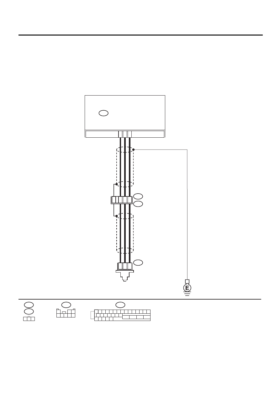
WIRING DIAGRAM:
ABS00312
F55
R70
F62
ABS CONTROL MODULE AND
HYDRAULIC CONTROL UNIT
ABS
G SENSOR
F49
2
1
3
F49
1 2 3 4 5 6 7 8 9 10 11 12 13 14 15
16 17 18 19 20 21 22
27 28 29 30 31
23
24
25
26
3
7
6
28
1
2
3
F55
R49
R70
2
8
30
1
2 3
4 5 6 7 8

ABS-147
ABS (DIAGNOSTICS)
DIAGNOSTICS CHART WITH SUBARU SELECT MONITOR
Step
Value
Yes
No
1
CHECK WHEELS FOR FREE TURNING.
Have the wheels been turned freely such as
when the vehicle is lifted up, or operated on a
rolling road?
Wheel have not turned freely.
The ABS is nor-
mal. Erase the
trouble code.
2
CHECK OUTPUT OF G SENSOR USING SE-
LECT MONITOR.
1) Select “Current data display & Save” on the
select monitor.
2) Read the select monitor display.
Is the G sensor output on the monitor dis-
play within the specified range when the
vehicle is in horizontal position?
2.1 - 2.5 V
3
CHECK OUTPUT OF G SENSOR USING SE-
LECT MONITOR.
1) Turn ignition switch to OFF.
2) Remove console box.
3) Remove G sensor from vehicle. (Do not
disconnect connector.)
4) Turn ignition switch to ON.
5) Select “Current data display & Save” on the
select monitor.
6) Read the select monitor display.
Is the G sensor output on the monitor dis-
play within the specified range when G
sensor is inclined forwards to 90
°
?
3.7 - 4.1 V
Replace G sen-
sor. <Ref. to ABS-
21, G Sensor.>
4
CHECK OUTPUT OF G SENSOR USING SE-
LECT MONITOR.
Read the select monitor display.
Is the G sensor output on the monitor display
within the specified range when G sensor is
inclined backwards to 90
°
?
0.5 - 0.9 V
Replace G sen-
sor. <Ref. to ABS-
21, G Sensor.>
5
CHECK POOR CONTACT IN CONNECTORS.
Turn ignition switch to OFF.
Is there poor contact in connector between
ABSCM&H/U and G sensor?
There is no poor contact.
Repair connector.
6
CHECK ABSCM&H/U.
1) Connect all connectors.
2) Erase the memory.
3) Perform inspection mode.
4) Read out the DTC.
Is the same DTC still being output?
Same DTC is not indicated.
Replace
ABSCM&H/U.
<Ref. to ABS-6,
ABS Control Mod-
ule and Hydraulic
Control Unit
(ABSCM&H/U).>
7
CHECK ANY OTHER DTC APPEARANCE.
Are other DTC being output?
Other DTC is not indicated.
A temporary poor
contact.
Proceed with the
diagnosis corre-
sponding to the
DTC.
8
CHECK OPEN CIRCUIT IN G SENSOR OUT-
PUT HARNESS AND GROUND HARNESS.
1) Turn ignition switch to OFF.
2) Disconnect connector from ABSCM&H/U.
3) Measure resistance between ABSCM&H/U
connector terminals.
Connector & terminal
(F49) No. 6 — No. 28:
Is the measured value within the specified
range?
5.0 - 5.6 k
Ω
Repair harness/
connector
between G sensor
and ABSCM&H/U.

ABS-148
ABS (DIAGNOSTICS)
DIAGNOSTICS CHART WITH SUBARU SELECT MONITOR
9
CHECK G SENSOR.
1) Remove console box.
2) Remove G sensor from vehicle.
3) Connect connector to G sensor.
4) Connect connector to ABSCM&H/U.
5) Turn ignition switch to ON.
6) Measure voltage between G sensor con-
nector terminals.
Connector & terminal
(R70) No. 2 (+) — No. 3 (
−−−−
):
Is the voltage within the specified range
when G sensor is horizontal?
2.1 - 2.5 V
Replace G sen-
sor. <Ref. to ABS-
21, G Sensor.>
10
CHECK G SENSOR.
Measure voltage between G sensor connector
terminals.
Connector & terminal
(R70) No. 2 (+) — No. 3 (
−−−−
):
Is the voltage within the specified range when
G sensor is inclined forwards to 90
°
?
3.7 - 4.1 V
Replace G sen-
sor. <Ref. to ABS-
21, G Sensor.>
11
CHECK G SENSOR.
Measure voltage between G sensor connector
terminals.
Connector & terminal
(R70) No. 2 (+) — No. 3 (
−−−−
):
Is the voltage within the specified range when
G sensor is inclined backwards to 90
°
?
0.5 - 0.9 V
Replace G sen-
sor. <Ref. to ABS-
21, G Sensor.>
12
CHECK ABSCM&H/U.
1) Turn ignition switch to OFF.
2) Connect all connectors.
3) Erase the memory.
4) Perform inspection mode.
5) Read out the DTC.
Is the same DTC still being output?
Same DTC is not indicated.
Replace
ABSCM&H/U.
<Ref. to ABS-6,
ABS Control Mod-
ule and Hydraulic
Control Unit
(ABSCM&H/U).>
13
CHECK ANY OTHER DTC APPEARANCE.
Are other DTC being output?
Other DTC is not indicated.
A temporary poor
contact.
Proceed with the
diagnosis corre-
sponding to the
DTC.
Step
Value
Yes
No

ABS-149
ABS (DIAGNOSTICS)
GENERAL DIAGNOSTICS TABLE
14.General Diagnostics Table
A: INSPECTION
Symptom
Probable faulty units/parts
Vehicle instability during braking
Vehicle pulls to either side.
• ABSCM&H/U (solenoid valve)
• ABS sensor
• Brake (caliper & piston, pads)
• Wheel alignment
• Tire specifications, tire wear and air pressures
• Incorrect wiring or piping connections
• Road surface (uneven, camber)
Vehicle spins.
• ABSCM&H/U (solenoid valve)
• ABS sensor
• Brake (pads)
• Tire specifications, tire wear and air pressures
• Incorrect wiring or piping connections
Poor braking
Long braking/stopping distance
• ABSCM&H/U (solenoid valve)
• Brake (pads)
• Air in brake line
• Tire specifications, tire wear and air pressures
• Incorrect wiring or piping connections
Wheel locks.
• ABSCM&H/U (solenoid valve, motor)
• ABS sensor
• Incorrect wiring or piping connections
Brake dragging
• ABSCM&H/U (solenoid valve)
• ABS sensor
• Master cylinder
• Brake (caliper & piston)
• Parking brake
• Axle & wheels
• Brake pedal play
Long brake pedal stroke
• Air in brake line
• Brake pedal play
Vehicle pitching
• Suspension play or fatigue (reduced damping)
• Incorrect wiring or piping connections
• Road surface (uneven)
Unstable or uneven braking
• ABSCM&H/U (solenoid valve)
• ABS sensor
• Brake (caliper & piston, pads)
• Tire specifications, tire wear and air pressures
• Incorrect wiring or piping connections
• Road surface (uneven)
Vibration and/or noise
(while driving on slippery roads)
Excessive pedal vibration
• Incorrect wiring or piping connections
• Road surface (uneven)
Noise from ABSCM&H/U
• ABSCM&H/U (mount bushing)
• ABS sensor
• Brake piping
Noise from front of vehicle
• ABSCM&H/U (mount bushing)
• ABS sensor
• Master cylinder
• Brake (caliper & piston, pads, rotor)
• Brake piping
• Brake booster & check valve
• Suspension play or fatigue
Noise from rear of vehicle
• ABS sensor
• Brake (caliper & piston, pads, rotor)
• Parking brake
• Brake piping
• Suspension play or fatigue
Нет комментариевНе стесняйтесь поделиться с нами вашим ценным мнением.
Текст