Subaru Legacy III (2000-2003 year). Service manual — part 919
LI-10
LIGHTING SYSTEM
HEADLIGHT BEAM LEVELER SYSTEM
9. Headlight Beam Leveler Sys-
tem
A: SCHEMATIC
1. HEADLIGHT BEAM LEVELER
<Ref. to WI-234, SCHEMATIC, Headlight Beam
Leveler System.>
B: INSPECTION
1. HEADLIGHT BEAM LEVELER ACTUA-
TOR
1) Turn on the headlights.
2) Confirm the headlight beam level is lowered by
changing the switch position to 0 - 1 - 2 - 3 - 4 - 5.
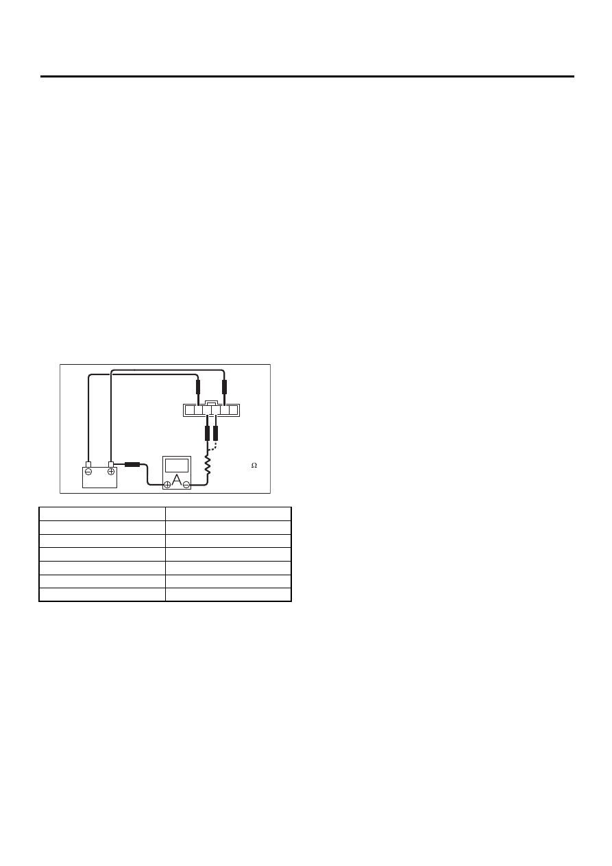
2. HEADLIGHT BEAM LEVELER SWITCH
Connect battery, headlight beam leveler switch
connector, circuit tester and resistor (500 to 800
Ω
)
as shown in the figure. Measure the current at each
switch position.
Switch position
Current (mA)
0
8.0
1
7.2
2
6.39
3
5.59
4
4.78
5
3.98
LI-00127
RH
500 – 800
LH
6 5 4 3 2 1
LI-11
LIGHTING SYSTEM
COMBINATION SWITCH (LIGHT)
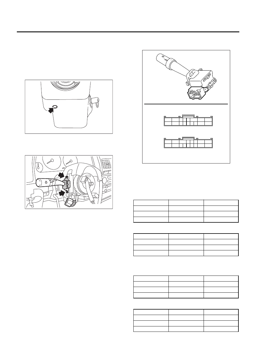
10.Combination Switch (Light)
A: REMOVAL
1) Disconnect ground cable from battery.
2) Remove instrument panel lower cover. <Ref. to
EI-35, REMOVAL, Instrument Panel Assembly.>
3) Remove screws which secure upper column
cover to lower column cover.
4) Disconnect connector from combination switch.
5) Remove screws which secure switch and re-
move switch.
B: INSTALLATION
Install in the reverse order of removal.
C: INSPECTION
Measure combination switch resistance.
1. LIGHTING SWITCH
LHD model and RHD model with rear fog light:
RHD model without rear fog light:
2. DIMMER AND PASSING SWITCH
LHD model and RHD model with rear fog light:
RHD model without rear fog light:
LI-00009
LI-00010
(A) LHD model and RHD model with rear fog light
(B) RHD model without rear fog light
Switch position
Terminal No.
Standard
OFF
—
More than 1 M
Ω
Tail
14 and 16
Less than 1
Ω
Head
13, 14 and 16
Less than 1
Ω
Switch position
Terminal No.
Standard
OFF
—
More than 1 M
Ω
Tail
9 and 15
Less than 1
Ω
Head
9, 14 and 15
Less than 1
Ω
Switch position
Terminal No.
Standard
Passing
7, 8 and 16
Less than 1
Ω
Low beam
16 and 17
Less than 1
Ω
High beam
7 and 16
Less than 1
Ω
Switch position
Terminal No.
Standard
Passing
1, 2 and 9
Less than 1
Ω
Low beam
9 and 10
Less than 1
Ω
High beam
2 and 9
Less than 1
Ω
LI-00184
1514131211 10
9
17
16
6 5 4
3
2
1
8
7
1514131211 10
9
17
16
6
5 4 3
2
1
8
7
(A)
(B)
LI-12
LIGHTING SYSTEM
COMBINATION SWITCH (LIGHT)
3. TURN SIGNAL SWITCH
LHD model and RHD model with rear fog light:
RHD model without rear fog light:
Switch position
Terminal No.
Standard
Left
1 and 2
Less than 1
Ω
Neutral
—
More than 1 M
Ω
Right
2 and 3
Less than 1
Ω
Switch position
Terminal No.
Standard
Left
6 and 7
Less than 1
Ω
Neutral
—
More than 1 M
Ω
Right
7 and 8
Less than 1
Ω
LI-13
LIGHTING SYSTEM
COMBINATION BASE SWITCH ASSEMBLY
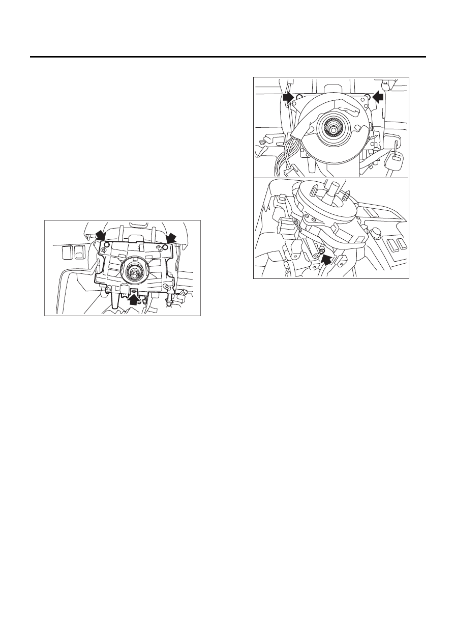
11.Combination Base Switch
Assembly
A: REMOVAL
1. WITHOUT VDC MODEL
1) Remove driver’s airbag module. <Ref. to AB-12,
REMOVAL, Driver's Airbag Module.>
2) Remove steering wheel. <Ref. to PS-24, RE-
MOVAL, Steering Wheel.>
3) Remove steering column cover.
4) Remove combination switch. <Ref. to LI-11, RE-
MOVAL, Combination Switch (Light).> <Ref. to
WW-8, REMOVAL, Combination Switch (Wiper).>
5) Loosen 4 screws and remove roll connector.
6) Loosen 3 screws.
7) Disconnect connector and remove combination
base switch assembly.
2. WITH VDC MODEL
1) Remove driver’s airbag module. <Ref. to AB-12,
REMOVAL, Driver's Airbag Module.>
2) Remove steering wheel. <Ref. to PS-24, RE-
MOVAL, Steering Wheel.>
3) Remove steering column cover.
4) Remove combination switch. <Ref. to LI-11, RE-
MOVAL, Combination Switch (Light).> <Ref. to
WW-8, REMOVAL, Combination Switch (Wiper).>
5) Loosen 3 screws.
6) Disconnect connector and remove combination
base switch assembly.
CAUTION:
In case of model with VDC, do not separate roll
connector from combination base switch.
B: INSTALLATION
1) Install in the reverse order of removal.
2) Align the attaching direction of roll connector
with steering wheel, before installation of steering
wheel.<Ref. to AB-19, ADJUSTMENT, Roll Con-
nector.>
C: INSPECTION
1. COMBINATION BASE SWITCH ASSEM-
BLY
Perform inspection for the following items and re-
place with a new one, if any damage is found.
• Crack or deformation of combination base switch
assembly or roll connector
CAUTION:
In case of model with VDC, do not separate roll
connector from combination base switch.
LI-00181
LI-00182
Нет комментариевНе стесняйтесь поделиться с нами вашим ценным мнением.
Текст