Subaru Legacy III (2000-2003 year). Service manual — part 918
LI-6
LIGHTING SYSTEM
TURN SIGNAL AND HAZARD LIGHT SYSTEM
5. Turn Signal and Hazard Light
System
A: SCHEMATIC
1. TURN SIGNAL LIGHT AND HAZARD
LIGHT LHD MODEL
<Ref. to WI-274, LHD MODEL, SCHEMATIC, Turn
Signal Light and Hazard Light System.>
2. TURN SIGNAL LIGHT AND HAZARD
LIGHT RHD MODEL
<Ref. to WI-276, RHD MODEL, Turn Signal Light
and Hazard Light System.>
B: INSPECTION
1. TURN SIGNAL SWITCH
<Ref. to LI-11, INSPECTION, Combination Switch
(Light).>
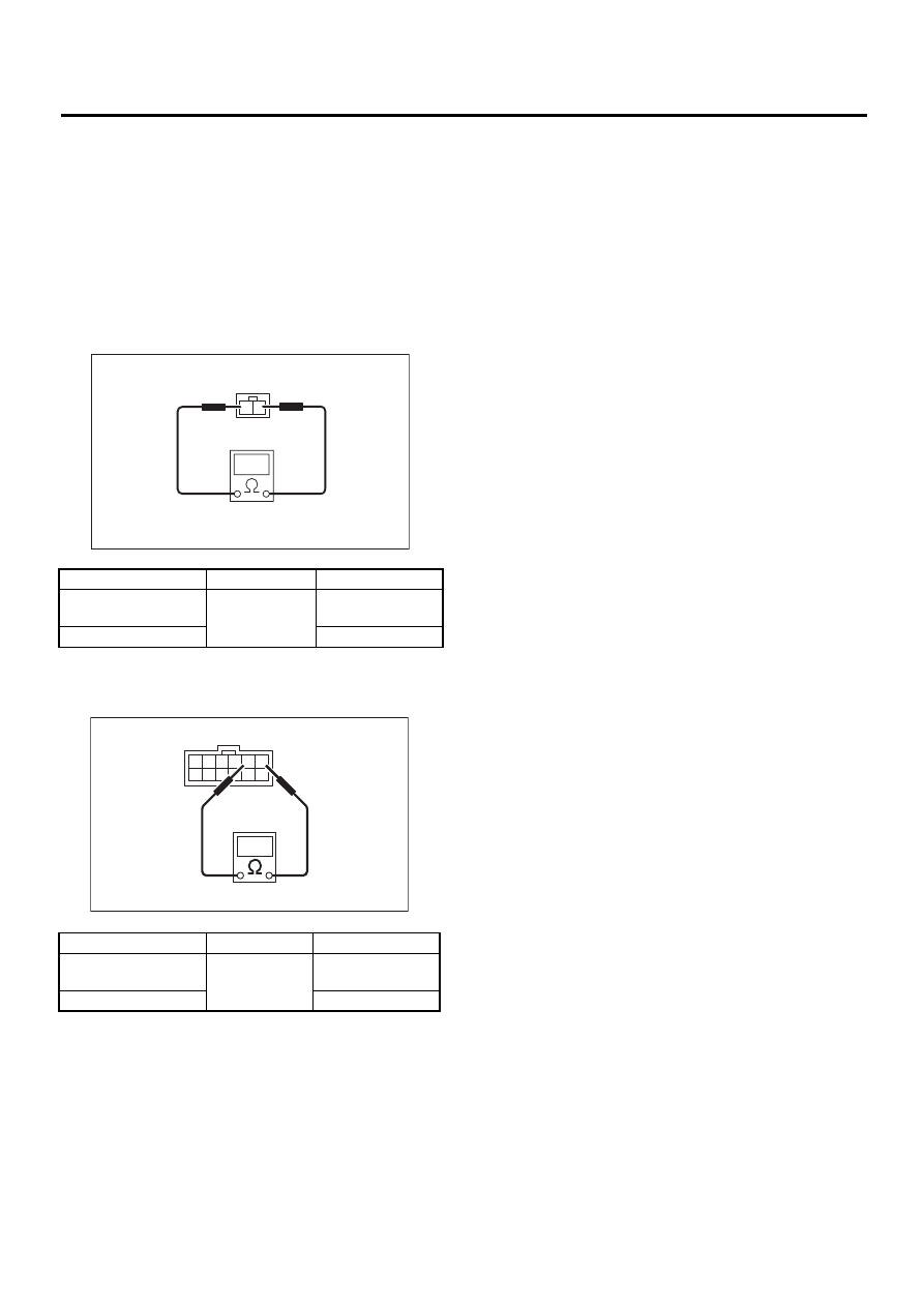
2. HAZARD SWITCH
Measure hazard switch resistance.
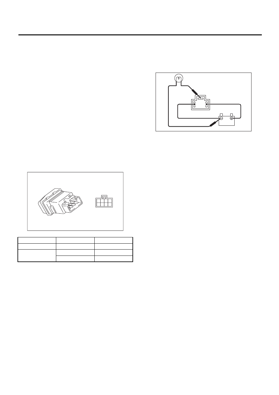
3. TURN SIGNAL & HAZARD MODULE
Connect battery and turn signal light bulb to the
module, as shown in the figure. The module is
properly functioning if it blinks when power is sup-
plied to the circuit.
Switch position
Terminal No.
Standard
OFF
6 and 7
Less than 1
Ω
ON
1, 3 and 4
Less than 1
Ω
7 and 8
Less than 1
Ω
LI-00002
8 7
5
6
4 3
1
2
LI-00003
LI-7
LIGHTING SYSTEM
BACK-UP LIGHT SYSTEM
6. Back-up Light System
A: SCHEMATIC
1. BACK-UP LIGHT
<Ref. to WI-247, SCHEMATIC, Back-up Light Sys-
tem.>
B: INSPECTION
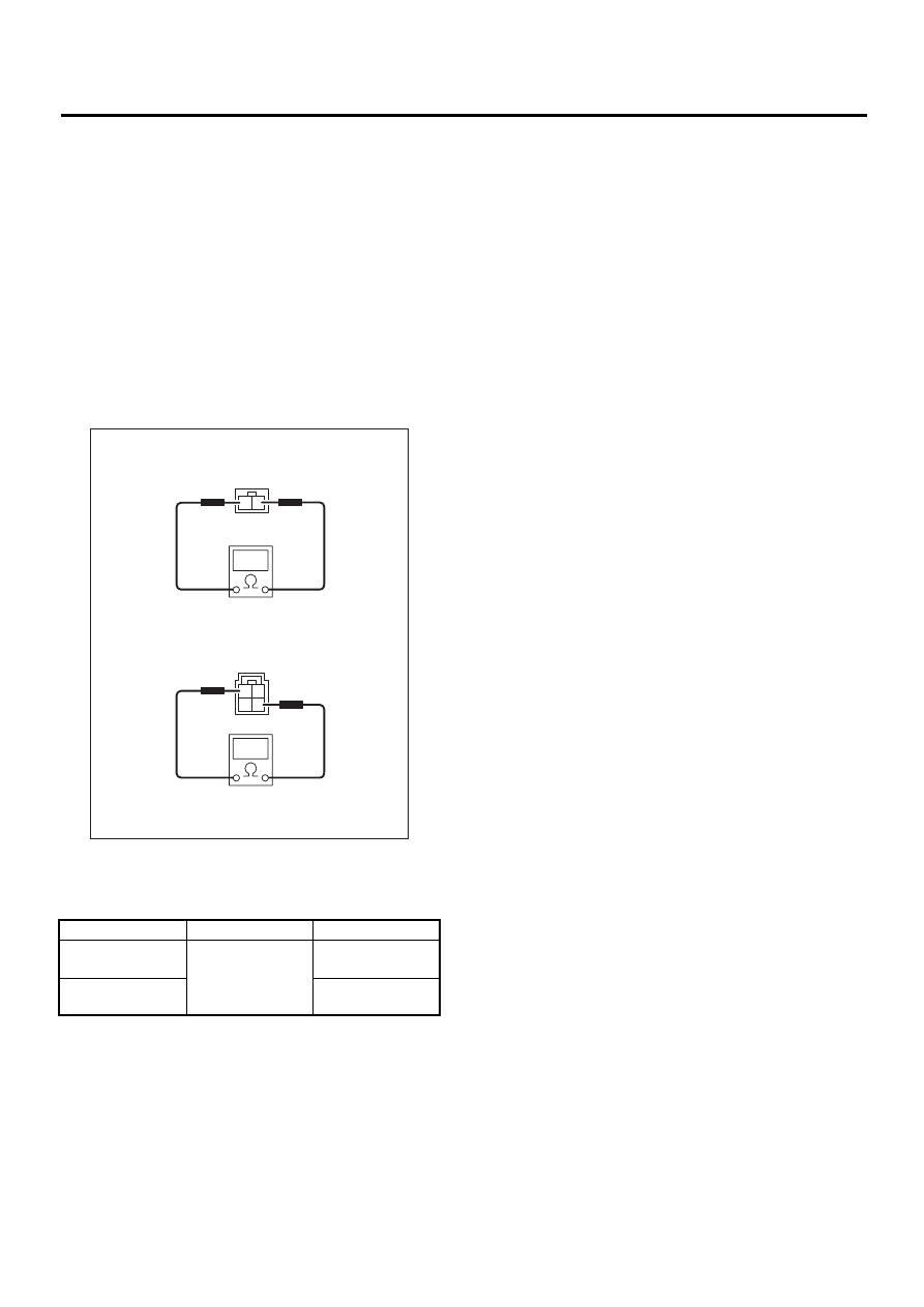
1. BACK-UP LIGHT SWITCH (M/T)
Measure back-up light switch resistance.
2. INHIBITOR SWITCH (A/T)
Measure inhibitor switch resistance.
Switch position
Terminal No.
Standard
When shift lever is set
in reverse position
1 and 2
Less than 1
Ω
Other positions
More than 1 M
Ω
Switch position
Terminal No.
Standard
When select lever is
set in “R” position
1 and 2
Less than 1
Ω
Other positions
More than 1 M
Ω
LI-00006
1
2
10 9
LI-00005
1
2
3
4
5
7
12 11
8 7
LI-8
LIGHTING SYSTEM
STOP LIGHT SYSTEM
7. Stop Light System
A: SCHEMATIC
1. STOP LIGHT SEDAN MODEL
<Ref. to WI-272, SEDAN MODEL, SCHEMATIC,
Stop Light System.>
2. STOP LIGHT WAGON MODEL
<Ref. to WI-273, WAGON MODEL, SCHEMATIC,
Stop Light System.>
B: INSPECTION
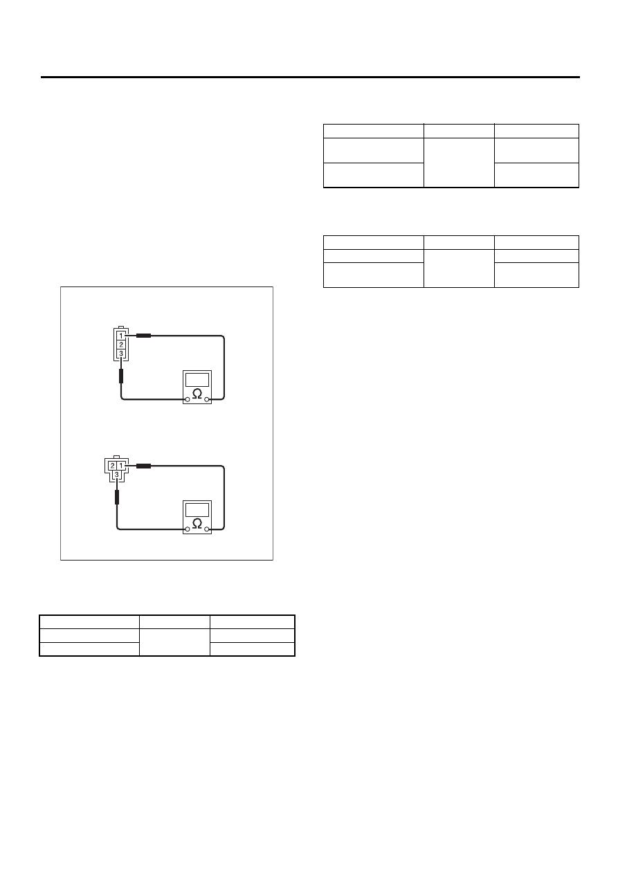
1. STOP LIGHT SWITCH
Measure stop light switch resistance.
(A) Without cruise control
(B) With cruise control
Switch position
Terminal No.
Standard
When brake pedal
is depressed
1 and 2: Without
cruise control
2 and 3: With
cruise control
Less than 1
Ω
When brake pedal
is released
More than 1 M
Ω
3
4
1
2
1
2
LI-00064
(A)
(B)
LI-9
LIGHTING SYSTEM
INTERIOR LIGHT SYSTEM
8. Interior Light System
A: SCHEMATIC
1. INTERIOR LIGHT LHD MODEL
<Ref. to WI-266, LHD MODEL, SCHEMATIC, In
Compartment Light System.>
2. INTERIOR LIGHT RHD MODEL
<Ref. to WI-269, RHD MODEL, SCHEMATIC, In
Compartment Light System.>
B: INSPECTION
1. DOOR SWITCH
Measure door switch resistance.
2. REAR GATE LATCH SWITCH
Measure rear gate latch switch.
3. TRUNK ROOM LIGHT SWITCH
Measure trunk room light switch.
(A) Front door switch
(B) Rear door switch
Switch position
Terminal No.
Standard
When door is open
1 and 3
Less than 1
Ω
When door is closed
More than 1 M
Ω
LI-00072
( A )
( B )
Switch position
Terminal No.
Standard
When rear gate is
open
1 and 2
Less than 1
Ω
When rear gate is
closed
More than 1 M
Ω
Switch position
Terminal No.
Standard
When trunk lid is open
1 and 2
Less than 1
Ω
When trunk lid is
closed
More than 1 M
Ω
Нет комментариевНе стесняйтесь поделиться с нами вашим ценным мнением.
Текст