Subaru Legacy III (2000-2003 year). Service manual — part 917
LI-2
LIGHTING SYSTEM
GENERAL DESCRIPTION
1. General Description
A: SPECIFICATIONS
B: PRECAUTIONS
• Before disassembling or reassembling parts, always disconnect battery ground cable. When replacing ra-
dio, control module, and other parts provided with memory functions, record memory contents before discon-
necting the battery ground cable. Otherwise, the memory will be erased.
• Reassemble in reverse order of disassembly, unless otherwise indicated.
• Adjust parts to the given specifications.
• Connect connectors and hoses securely during reassembly.
• After reassembly, make sure functional parts operate smoothly.
WARNING:
• Airbag system wiring harness is routed near electrical parts and switches. All airbag system wiring
harnesses and connectors are yellow. Do not use electric test equipment on these circuits.
• Be careful not to damage the airbag system wiring harness when servicing electrical parts and
switches.
C: PREPARATION TOOL
1. GENERAL TOOLS
Headlight
12 V — 55 W/55 W (Halogen)
Front turn signal light
12 V — 21 W
Side turn signal light
12 V — 5 W
Parking light
12 V — 5 W
Front fog light
12 V — 55 W
Rear fog light
12 V — 21 W
Rear combination light
Tail/Stop light
12 V — 5/21 W
Turn signal light
12 V — 21 W
Back-up light
12 V — 21 W
License plate light
12 V — 5 W
High-mounted stop light
Sedan
12 V — 21 W
Wagon
12 V — 10 W
Room light
12 V — 8 W
Spot light
12 V — 8 W
Door step light
12 V — 3.4 W
Luggage room light
12 V — 13 W
Trunk room light
12 V — 5 W
Glove box light
12 V — 1.4 W
TOOL NAME
REMARKS
Circuit Tester
Used for measuring resistance and voltage.
LI-3
LIGHTING SYSTEM
HEADLIGHT AND TAIL LIGHT SYSTEM
2. Headlight and Tail Light Sys-
tem
A: SCHEMATIC
1. HEADLIGHT LHD MODEL
<Ref. to WI-264, LHD MODEL, SCHEMATIC,
Headlight System.>
2. HEADLIGHT RHD MODEL
<Ref. to WI-265, RHD MODEL, SCHEMATIC,
Headlight System.>
3. CLEARANCE LIGHT AND ILLUMINA-
TION LIGHT LHD MODEL
<Ref. to WI-248, LHD 4-CYLINDER ENGINE
MODEL, SCHEMATIC, Clearance Light and Illumi-
nation Light System.>
<Ref. to WI-251, LHD 6-CYLINDER ENGINE
MODEL, SCHEMATIC, Clearance Light and Illumi-
nation Light System.>
4. CLEARANCE LIGHT AND ILLUMINA-
TION LIGHT RHD MODEL
<Ref. to WI-254, RHD 4-CYLINDER NON-TURBO
ENGINE MODEL, SCHEMATIC, Clearance Light
and Illumination Light System.>
<Ref. to WI-257, RHD 6-CYLINDER ENGINE AND
TURBO ENGINE MODEL, SCHEMATIC, Clear-
ance Light and Illumination Light System.>
B: INSPECTION
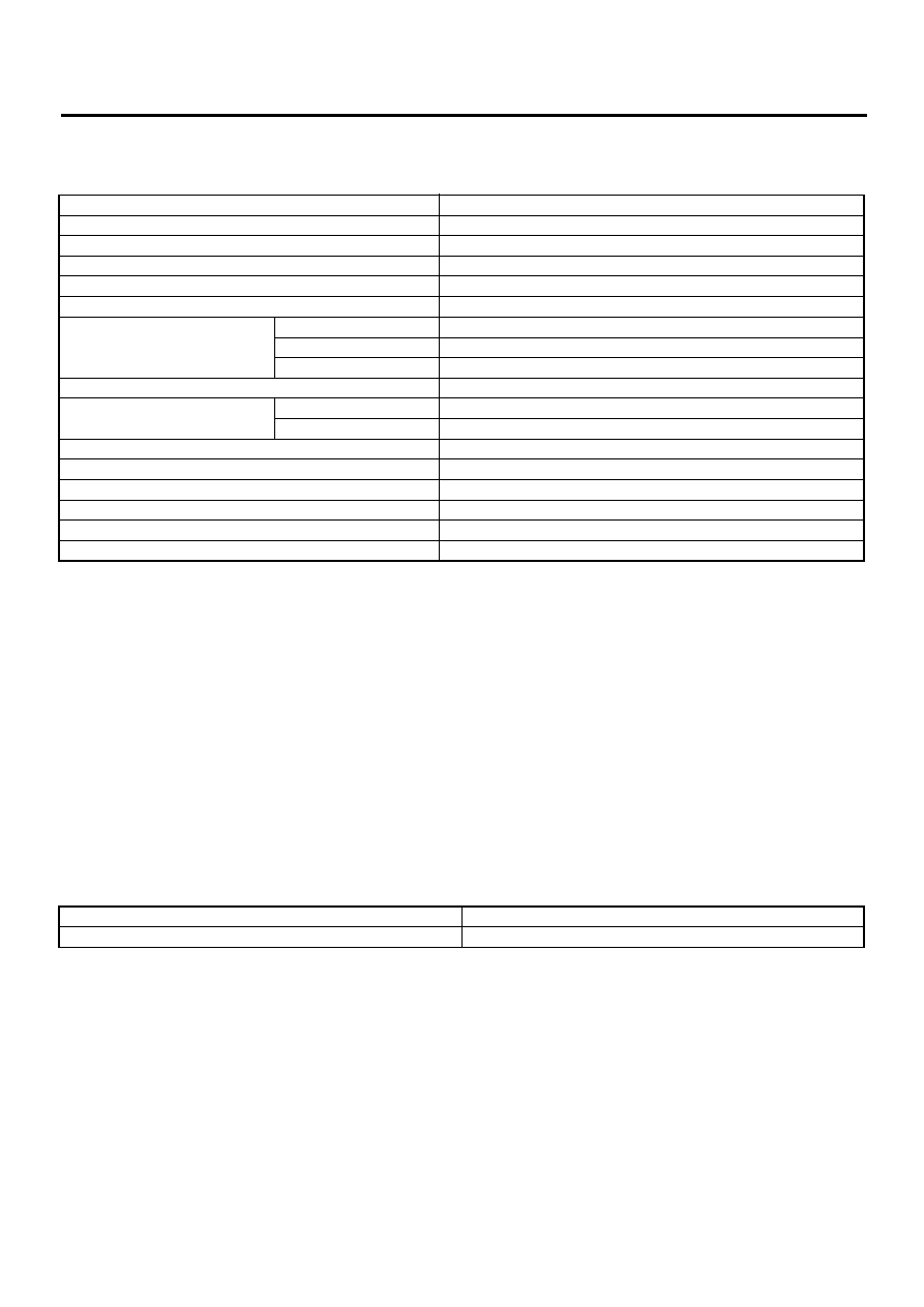
1. HEADLIGHT RELAY
Measure headlight relay resistance between termi-
nals while connecting terminal No. 4 to battery pos-
itive terminal No. 3 to battery ground terminal.
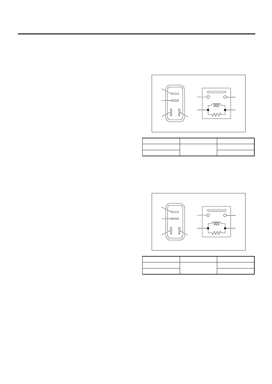
2. TAIL AND ILLUMINATION RELAY
Measure tail and illumination relay resistance be-
tween terminals while connecting terminal No. 4 to
battery positive terminal No. 3 to battery ground ter-
minal.
Current
Terminal No.
Standard
Flow
1 and 2
Less than 1
Ω
No flow
More than 1 M
Ω
Current
Terminal No.
Standard
Flow
1 and 2
Less than 1
Ω
No flow
More than 1 M
Ω
LI-00001
(1)
(2)
(1)
(4)
(2)
(3)
(3)
(4)
LI-00001
(1)
(2)
(1)
(4)
(2)
(3)
(3)
(4)
LI-4
LIGHTING SYSTEM
FRONT FOG LIGHT SYSTEM
3. Front Fog Light System
A: SCHEMATIC
1. FRONT FOG LIGHT 4 CYLINDER EN-
GINE MODEL
<Ref. to WI-260, 4-CYLINDER ENGINE MODEL,
SCHEMATIC, Front Fog Light System.>
2. FRONT FOG LIGHT LHD 6 CYLINDER
ENGINE MODEL
<Ref. to WI-261, LHD 6-CYLINDER ENGINE
MODEL, SCHEMATIC, Front Fog Light System.>
3. FRONT FOG LIGHT RHD 6 CYLINDER
ENGINE MODEL
<Ref. to WI-262, RHD 6-CYLINDER ENGINE
MODEL, SCHEMATIC, Front Fog Light System.>
B: INSPECTION
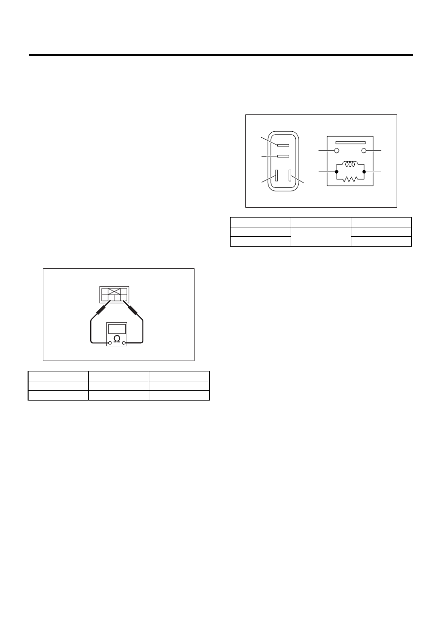
1. FRONT FOG LIGHT SWITCH
Measure front fog light switch resistance.
2. FRONT FOG LIGHT RELAY
Measure front fog light relay resistance between
terminals while connecting terminal No. 4 to battery
positive terminal and terminal No. 3 to battery
ground terminal.
Switch position
Terminal No.
Standard
OFF
—
More than 1 M
Ω
ON
3 and 5
Less than 1
Ω
LI-00051
1
2
3
6 5 4
Current
Terminal No.
Standard
Flow
1 and 2
Less than 1
Ω
No flow
More than 1 M
Ω
LI-00001
(1)
(2)
(1)
(4)
(2)
(3)
(3)
(4)
LI-5
LIGHTING SYSTEM
REAR FOG LIGHT SYSTEM
4. Rear Fog Light System
A: SCHEMATIC
1. REAR FOG LIGHT
<Ref. to WI-294, SCHEMATIC, Rear Fog Light
System.>
B: INSPECTION
1. REAR FOG LIGHT SWITCH
1) Turn ignition switch ON.
2) Turn on the headlight or front fog light.
3) Push the rear fog light switch and check if the
rear fog light turns on.
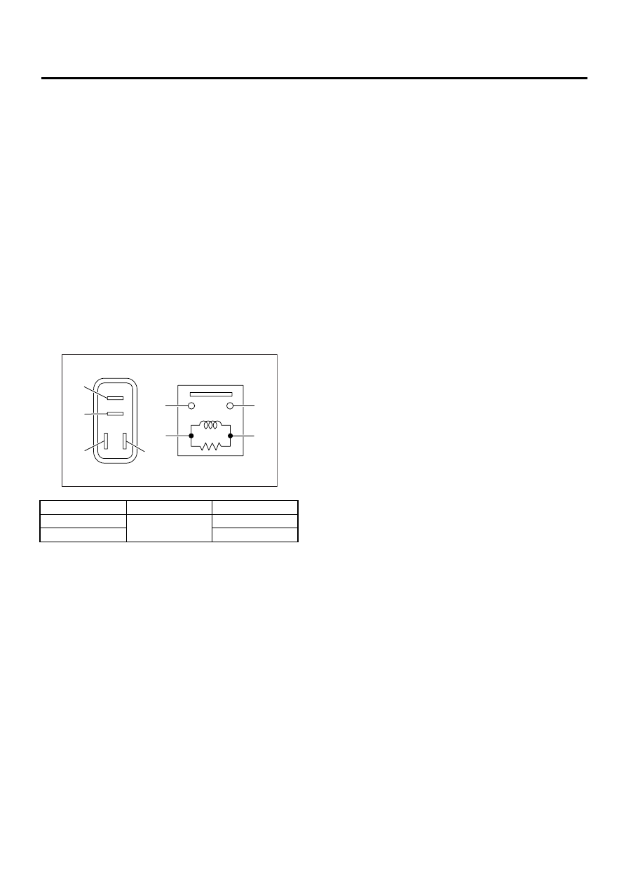
2. REAR FOG LIGHT RELAY
Measure rear fog light relay resistance between
terminals while connecting terminal No. 4 to battery
positive terminal and No. 3 to battery ground termi-
nal.
Current
Terminal No.
Standard
Flow
1 and 2
Less than 1
Ω
No flow
More than 1 M
Ω
LI-00001
(1)
(2)
(1)
(4)
(2)
(3)
(3)
(4)
Нет комментариевНе стесняйтесь поделиться с нами вашим ценным мнением.
Текст