Subaru Legacy III (2000-2003 year). Service manual — part 762
VDC-84
VDC (DIAGNOSTICS)
DIAGNOSTICS CHART WITH DIAGNOSIS CONNECTOR
AE:DTC 45 CONTROL MODULE OUT OF SPECIFICATION
DIAGNOSIS:
• Control module out of specification
TROUBLE SYMPTOM:
• ABS does not operate.
• VDC does not operate.
Step
Value
Yes
No
1
CHECK TCM.
Is the same diagnostic trouble code as in the
current diagnosis still being output?
Same DTC indicated.
Proceed with the
diagnosis corre-
sponding to the
diagnostic trouble
code.
2
CHECK VDCCM SPECIFICATIONS.
Check the VDCCM identification mark.
VDCCM identification mark
H4 engine model
K
OUTBACK H4 enigne model
M
OUTBACK H6 enigne model
N
H4 enigne model for Australia
J
H6 enigne model for Australia OUT-
BACK
Y
Does the VDCCM identification mark agree
with the vehicle specifications?
Agree.
Replace VDCCM.
<Ref. to VDC-8,
VDC Control Mod-
ule (VDCCM).>
3
CHECK TCM SPECIFICATIONS.
Check the TCM identification mark.
TCM identification mark
LHD H4 engine model
YZ
RHD H4 engine model
ZG
LHD OUTBACK H4 enigne model
ZB
RHD OUTBACK H4 enigne model
ZJ
LHD OUTBACK H6 enigne model
ZD
RHD OUTBACK H6 enigne model
ZL
Does the TCM identification mark agree with
the vehicle specifications?
Agree.
Replace TCM.
<Ref. to AT-76,
Transmission Con-
trol Module
(TCM).>
4
CHECK TCM.
1) Replace TCM. <Ref. to AT-76, Transmis-
2) Erase the memory.
3) Perform inspection mode.
4) Read out the diagnostic trouble code.
Is the same diagnostic trouble code as in
the current diagnosis still being output?
Same DTC indicated.
The original TCM
has been faulty.
VDC-85
VDC (DIAGNOSTICS)
DIAGNOSTICS CHART WITH DIAGNOSIS CONNECTOR
5
CHECK VDCCM.
1) Install original TCM.
2) Replace VDCCM. <Ref. to VDC-8, VDC
3) Erase the memory.
4) Perform inspection mode.
5) Read out the diagnostic trouble code.
Is the same diagnostic trouble code as in
the current diagnosis still being output?
Same DTC indicated.
The original
VDCCM has been
faulty.
6
CHECK VDCCM.
Is the same diagnostic trouble code as in the
current diagnosis still being output?
Same DTC indicated.
Replace TCM.
<Ref. to AT-76,
Transmission Con-
trol Module
(TCM).>
Proceed with the
diagnosis corre-
sponding to the
diagnostic trouble
code.
Step
Value
Yes
No
VDC-86
VDC (DIAGNOSTICS)
DIAGNOSTICS CHART WITH DIAGNOSIS CONNECTOR
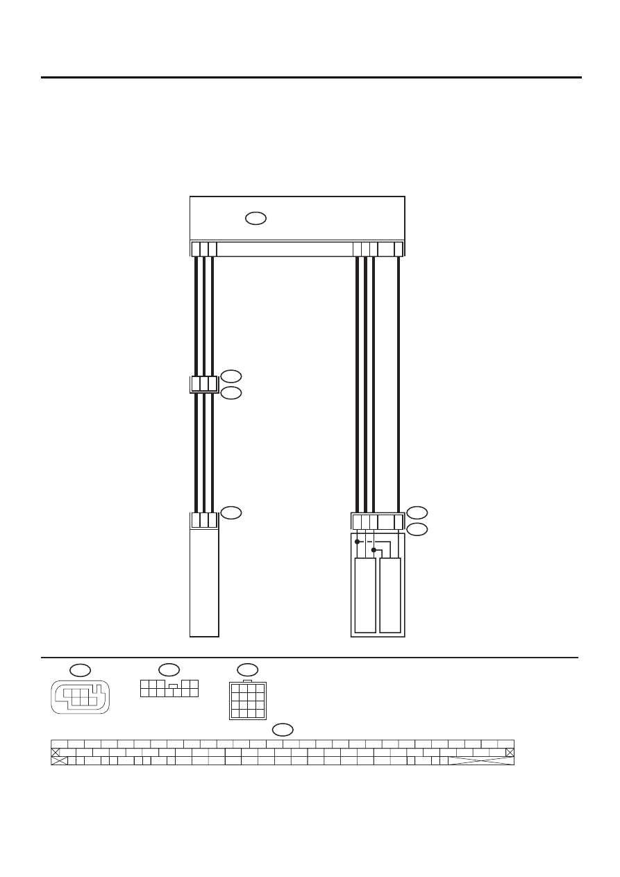
AF:DTC 46 ABNORMAL VOLTAGE OF 5 V POWER SUPPLY
DIAGNOSIS:
• 5 volt power supply is abnormal.
TROUBLE SYMPTOM:
• ABS does not operate.
• VDC does not operate.
WIRING DIAGRAM:
VDC00177
VDC CONTROL MODULE
63
70
64
76
77
78
15
13
16
36
14
5
3
6
10
12
9
F87
YAW RATE AND
LATERAL G SENSOR
F55
R49
R100
VDC HYDRAULIC UNIT
F91
VDC5
PRIMAR
Y
PRESSURE SENSOR
SECOND
AR
Y
PRESSURE SENSOR
F55
1 2 3
4 5
6 7 8 9 10 11 12
F91
1
2
3
4
5
6
7
8
9
10
11
12
13
14
15
16
R100
F87
56 57
59 60
62 63
65
82 83
80
27
28
25
26
23
24
21
22
19
20
17
18
15
16
13
14
11
12
9
10
7
8
5
6
3
4
1
2
54
55
52
53
50
51
81
48
49
46
47
44
45
78
79
76
77
75
42
43
40
41
74
72
73
70
71
39
37
38
35
36
69
67
68
66
33
34
61
64
31
32
29
30
58
1
3
4 5 6
2
VDC-87
VDC (DIAGNOSTICS)
DIAGNOSTICS CHART WITH DIAGNOSIS CONNECTOR
Step
Value
Yes
No
1
CHECK GROUND SHORT OF SENSOR AND
HARNESS.
1) Turn ignition switch OFF.
2) Disconnect connector from VDCCM.
3) Measure resistance between VDCCM con-
nector and chassis ground.
Connector & terminal
(F87) No. 63 — Chassis ground (Lateral
G sensor):
(F87) No. 78 — Chassis ground (Pres-
sure sensor):
Does the measured value exceed the spec-
ified value?
1 M
Ω
2
CHECK GROUND SHORT OF HARNESS.
1) Disconnect connector from faulty sensors.
2) Measure resistance between VDCCM and
chassis ground.
Connector & terminal
(F87) No. 63 — Chassis ground (Lateral
G sensor):
(F87) No. 78 — Chassis ground (Pres-
sure sensor):
Does the measured value exceed the spec-
ified value?
1 M
Ω
Replace faulty
sensors.
Repair or replace
harness connec-
tor between
VDCCM and faulty
sensor.
3
CHECK BATTERY SHORT OF SENSOR AND
HARNESS.
Measure voltage between VDCCM and chas-
sis ground.
Connector & terminal
(F87) No. 63 (+) — Chassis ground (
−−−−
)
(Lateral G sensor):
(F87) No. 78 (+) — Chassis ground (
−−−−
)
(Pressure sensor):
Is the measured value less than the specified
value?
0.5 V
4
CHECK BATTERY SHORT OF SENSOR AND
HARNESS.
1) Turn ignition switch to ON.
2) Measure voltage between VDCCM connec-
tor and chassis ground.
Connector & terminal
(F87) No. 63 (+) — Chassis ground (
−−−−
)
(Lateral G sensor):
(F87) No. 78 (+) — Chassis ground (
−−−−
)
(Pressure sensor):
Is the measured value less than the speci-
fied value?
0.5 V
Replace VDCCM.
<Ref. to VDC-8,
VDC Control Mod-
ule (VDCCM).>
5
CHECK BATTERY SHORT OF HARNESS.
1) Turn ignition switch to OFF.
2) Disconnect connector from faulty sensors.
3) Measure voltage between VDCCM and
chassis ground.
Connector & terminal
(F87) No. 63 (+) — Chassis ground (
−−−−
)
(Lateral G sensor):
(F87) No. 78 (+) — Chassis ground (
−−−−
)
(Pressure sensor):
Is the measured value less than the speci-
fied value?
0.5 V
Repair or replace
harness connec-
tor between
VDCCM and faulty
sensor.
Нет комментариевНе стесняйтесь поделиться с нами вашим ценным мнением.
Текст