Subaru Legacy III (2000-2003 year). Service manual — part 763

VDC-88
VDC (DIAGNOSTICS)
DIAGNOSTICS CHART WITH DIAGNOSIS CONNECTOR
6
CHECK BATTERY SHORT OF HARNESS.
1) Turn ignition switch to ON.
2) Measure voltage between VDCCM and
chassis ground.
Connector & terminal
(F87) No. 63 (+) — Chassis ground (
−−−−
)
(Lateral G sensor):
(F87) No. 78 (+) — Chassis ground (
−−−−
)
(Pressure sensor):
Is the measured value less than the speci-
fied value?
0.5 V
Replace faulty
sensor.
Repair or replace
harness connec-
tor between
VDCCM and faulty
sensor.
Step
Value
Yes
No
VDC-89
VDC (DIAGNOSTICS)
DIAGNOSTICS CHART WITH DIAGNOSIS CONNECTOR
MEMO:
VDC-90
VDC (DIAGNOSTICS)
DIAGNOSTICS CHART WITH DIAGNOSIS CONNECTOR
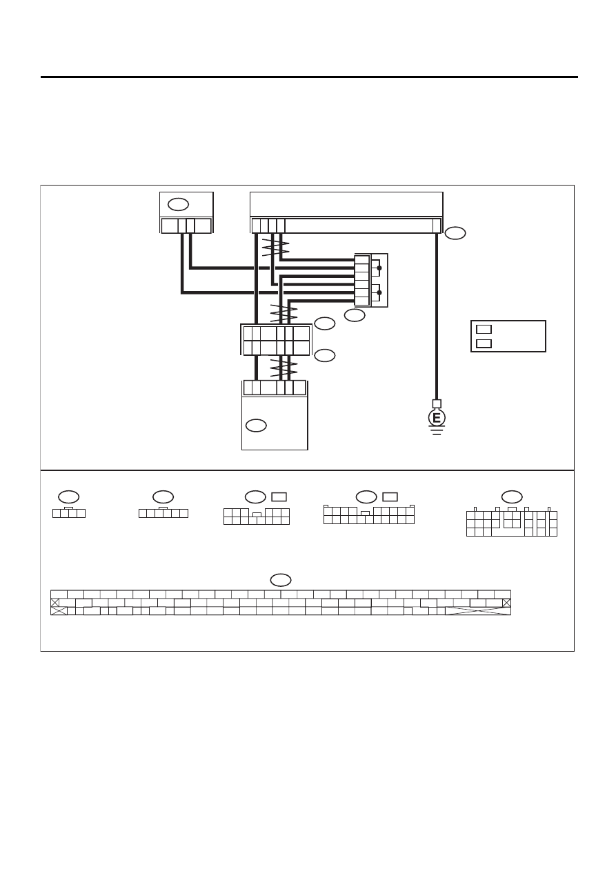
AG:DTC 47 FAULTY CAN COMMUNICATION LINE
DIAGNOSIS:
• CAN communication line is broken or short circuited.
TROUBLE SYMPTOM:
• ABS does not operate.
• VDC does not operate.
WIRING DIAGRAM:
VDC00178
B234
STEERING ANGLE SENSOR
9
18
4
2
1
3
2
3
1
5
6
4
81
27
83
1
15
R
2
5
9
L
6
B231
VDC
CONTROL
MODULE
F96
B225
F87
B56
1 2
7
8
9
5 6
3 4
10 11 12
19 20 21
13
14 15
16
17
18
22
23
24
B231
1 2 3 4
B234
1 2 3 4 5 6
F87
56 57
59 60
62 63
65
82 83
80
27
28
25
26
23
24
21
22
19
20
17
18
15
16
13
14
11
12
9
10
7
8
5
6
3
4
1
2
54
55
52
53
50
51
81
48
49
46
47
44
45
78
79
76
77
75
42
43
40
41
74
72
73
70
71
39
37
38
35
36
69
67
68
66
33
34
61
64
31
32
29
30
58
B56
TCM
1 2 3
4 5 6
7 8 9 10 11 12 13 14
F96
L
:
F96
R
:
R
L
1 2 3 4
5 6 7 8 9
10 11 12 13 14 15 16 17 18 19 20
: RHD MODEL
: LHD MODEL

VDC-91
VDC (DIAGNOSTICS)
DIAGNOSTICS CHART WITH DIAGNOSIS CONNECTOR
Step
Value
Yes
No
1
CHECK HARNESS BETWEEN VDCCM,
STEERING ANGLE SENSOR AND TCM.
1) Turn ignition switch OFF.
2) Disconnect connector from VDCCM, TCM
and steering angle sensor.
3) Measure resistance between VDCCM,
TCM and steering angle sensor.
Connector & terminal
(F87) No. 83 — (B56) No. 9:
(F87) No. 81 — (B56) No. 18:
(F87) No. 83 — (B231) No. 2:
(F87) No. 81 — (B231) No. 1:
Is the measured value less than the speci-
fied value?
0.5
Ω
2
CHECK HARNESS BETWEEN STEERING
ANGLE SENSOR AND TCM.
Measure resistance between TCM and steer-
ing angle sensor.
Connector & terminal
(B56) No. 9 — (B231) No. 2:
(B56) No. 18 — (B231) No. 1:
Is the measured value less than the specified
value?
0.5
Ω
Repair or replace
harness connec-
tor between
VDCCM and
steering angle
sensor.
Repair or replace
harness connec-
tor between TCM
and steering angle
sensor.
3
CHECK GROUND SHORT OF HARNESS.
Measure resistance between VDCCM and
chassis ground.
Connector & terminal
(F87) No. 83 — Chassis ground:
(F87) No. 81 — Chassis ground:
Does the measured value exceed the specified
value?
1 M
Ω
Repair or replace
harness connec-
tor between
VDCCM, TCM and
steering angle
sensor.
4
CHECK BATTERY SHORT OF SENSOR.
Measure voltage between VDCCM and chas-
sis ground.
Connector & terminal
(F87) No. 83 — Chassis ground:
(F87) No. 81 — Chassis ground:
Is the measured value less than the specified
value?
0.5 V
Repair or replace
harness connec-
tor between
VDCCM, TCM and
steering angle
sensor.
5
CHECK BATTERY SHORT OF SENSOR.
1) Turn ignition switch to ON.
2) Measure voltage between VDCCM and
chassis ground.
Connector & terminal
(F87) No. 83 — Chassis ground:
(F87) No. 81 — Chassis ground:
Is the measured value less than the speci-
fied value?
0.5 V
Repair or replace
harness connec-
tor between
VDCCM, TCM and
steering angle
sensor.
6
CHECK STEERING ANGLE SENSOR.
1) Turn ignition switch to OFF.
2) Connect connector to steering angle sen-
sor.
3) Measure resistance between VDCCM con-
nector terminals.
Connector & terminal
(F87) No. 83 — No. 81:
Is the measured value within the specified
range?
114 — 126
Ω
Нет комментариевНе стесняйтесь поделиться с нами вашим ценным мнением.
Текст