Subaru Legacy III (2000-2003 year). Service manual — part 760
VDC-76
VDC (DIAGNOSTICS)
DIAGNOSTICS CHART WITH DIAGNOSIS CONNECTOR
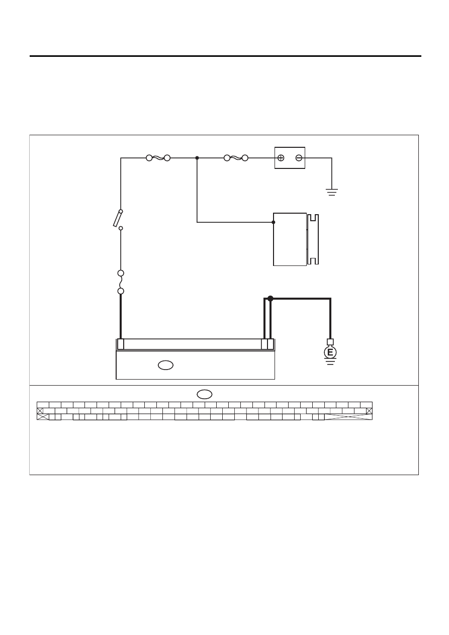
AB:DTC 42 SOURCE VOLTAGE IS ABNORMAL.
DIAGNOSIS:
• Power source voltage of the VDCCM is low.
TROUBLE SYMPTOM:
• ABS does not operate.
• VDC does not operate.
WIRING DIAGRAM:
VDC00144
VDC CONTROL MODULE
1
55
28
F87
SBF-1
GENERATOR
SBF-4
IGNITION
SWITCH
F87
56 57
59 60
62 63
65
82 83
80
27
28
25
26
23
24
21
22
19
20
17
18
15
16
13
14
11
12
9
10
7
8
5
6
3
4
1
2
54
55
52
53
50
51
81
48
49
46
47
44
45
78
79
76
77
75
42
43
40
41
74
72
73
70
71
39
37
38
35
36
69
67
68
66
33
34
61
64
31
32
29
30
58
BATTERY
NO
. 18 15A
VDC-77
VDC (DIAGNOSTICS)
DIAGNOSTICS CHART WITH DIAGNOSIS CONNECTOR
Step
Value
Yes
No
1
CHECK GENERATOR.
1) Start engine.
2) Idling after warm-up.
3) Measure voltage between generator B ter-
minal and chassis ground.
Terminal
Generator B terminal — Chassis
ground:
Is the measured value within the specified
range?
10 — 15 V
Repair generator.
2
CHECK BATTERY TERMINAL.
Turn ignition switch to OFF.
Are the positive and negative battery terminals
tightly clamped?
Clamped securely.
Tighten the clamp
of terminal.
3
CHECK INPUT VOLTAGE OF VDCCM.
1) Disconnect connector from VDCCM.
2) Run the engine at idle.
3) Measure voltage between VDCCM connec-
tor and chassis ground.
Connector & terminal
(F87) No. 28 (+) — Chassis ground (
−−−−
):
Is the measured value within the specified
range?
10 — 15 V
Repair harness
connector
between battery,
ignition switch and
VDCCM.
4
CHECK GROUND CIRCUIT OF VDCCM.
1) Turn ignition switch to OFF.
2) Measure resistance between VDCCM con-
nector and chassis ground.
Connector & terminal
(F87) No. 1 — Chassis ground:
(F87) No. 55 — Chassis ground:
Is the measured value less than the speci-
fied value?
0.5
Ω
Repair VDCCM
ground harness.
5
CHECK POOR CONTACT IN CONNECTORS.
Is there poor contact in connectors between
generator, battery and VDCCM?
There is poor contact.
Repair connector.
6
CHECK VDCCM.
1) Connect all connectors.
2) Erase the memory.
3) Perform inspection mode.
4) Read out the diagnostic trouble code.
Is the same diagnostic trouble code as in
the current diagnosis still being output?
Same DTC indicated.
Replace VDCCM.
<Ref. to VDC-8,
VDC Control Mod-
ule (VDCCM).>
7
CHECK ANY OTHER DIAGNOSTIC TROU-
BLE CODES APPEARANCE.
Are other diagnostic trouble codes being out-
put?
Other DTC indicated.
Proceed with the
diagnosis corre-
sponding to the
diagnostic trouble
code.
A temporary poor
contact.
VDC-78
VDC (DIAGNOSTICS)
DIAGNOSTICS CHART WITH DIAGNOSIS CONNECTOR
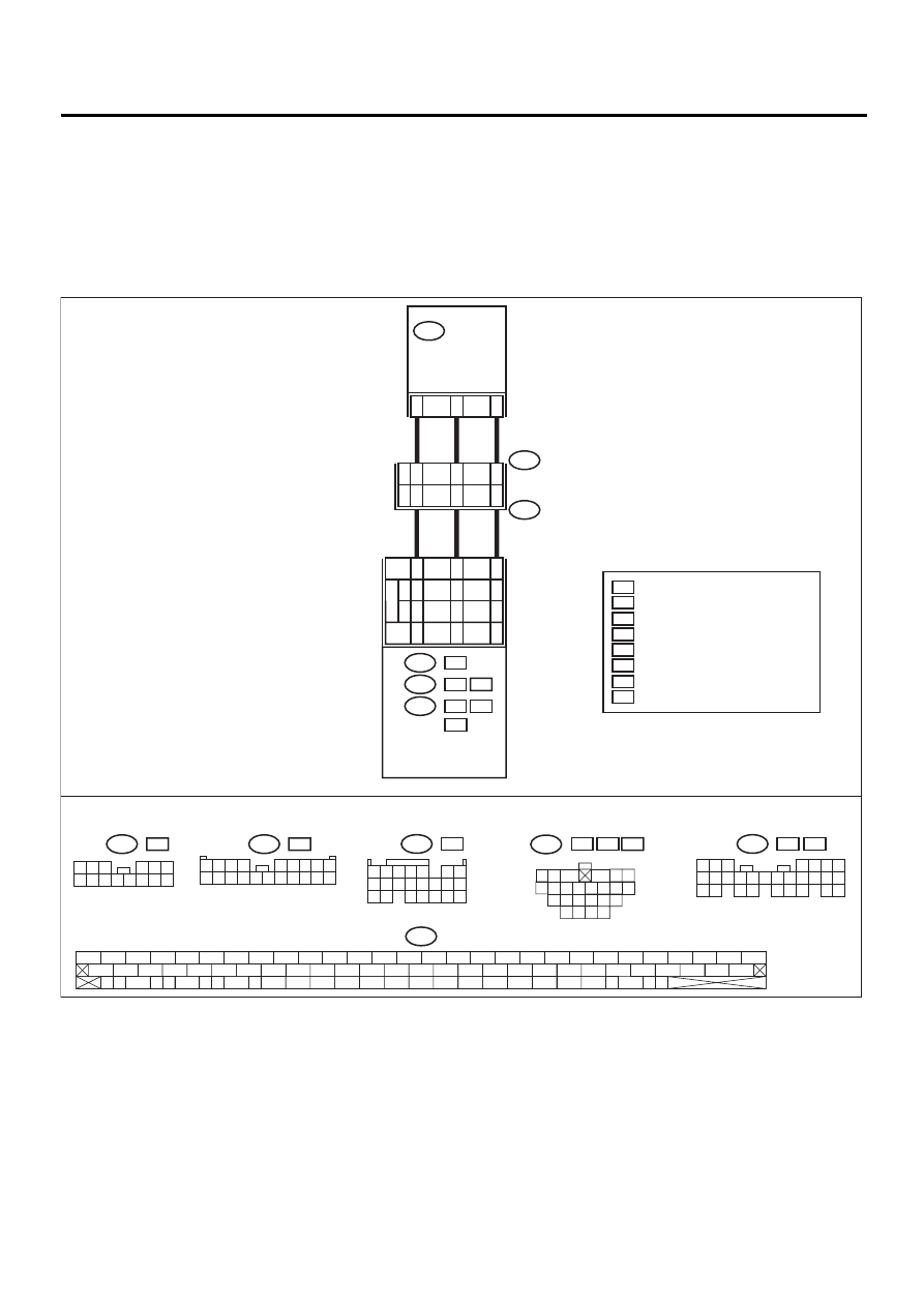
AC:DTC 43 FAULTY VDCCM — ECM COMMUNICATION LINE
DIAGNOSIS:
• AET communication line is broken or short circuited.
• AEB communication line is broken or short circuited.
• AEC communication line is broken or short circuited.
TROUBLE SYMPTOM:
• VDC does not operate.
WIRING DIAGRAM:
C8
C7
C2
C8
C7
LH4
RH4
WO
C2
B5
A12
OO
B18
A4
B6
H6
A11
VDC
CONTROL
MODULE
AET
AEB
AEC
5
7
R
21
43
8
6
1
4
L
2
F87
F96
B255
F87
56 57
59 60
62 63
65
82 83
80
27
28
25
26
23
24
21
22
19
20
17
18
15
16
13
14
11
12
9
10
7
8
5
6
3
4
1
2
54
55
52
53
50
51
81
48
49
46
47
44
45
78
79
76
77
75
42
43
40
41
74
72
73
70
71
39
37
38
35
36
69
67
68
66
33
34
61
64
31
32
29
30
58
B135
ENGINE
CONTROL
MODULE
B134
B135
A:
:
B:
:
H6
RH4 WO
B136
C:
: LH4
OO
RH4
B:
: RH4 WO
: LH4 RH4 OO
B134
A:
: H6
5 6 7
8
2
1
9
4
3
10
24
22 23
25
11 12 13 14 15
26
27 28
16 17 18 19
20 21
1 2 3 4
10 11 12
19 20 21
13
5
6
14 15
7
8 9
16 17
18
22
1 2 3
4 5 6
7 8 9 10 11 12 13 14
F96
L
:
F96
R
:
1 2 3 4
5 6 7 8 9
10 11 12 13 14 15 16 17 18 19 20
VDC00175
C: B136
3
4
1 2
8 9 10 11 12 13 14
15 16 17 18 19 20
21 22 23 24
5 6
7
: 4 CYLINDER ENGINE RHD MODEL
: 4 CYLINDER ENGINE LHD MODEL
RH4
LH4
: 4 CYLINDER ENGINE
: 6 CYLINDER ENGINE
H4
H6
: RHD MODEL
: LHD MODEL
R
L
: WITHOUT OBD MODEL
: WITH OBD MODEL
OO
WO
VDC-79
VDC (DIAGNOSTICS)
DIAGNOSTICS CHART WITH DIAGNOSIS CONNECTOR
Step
Value
Yes
No
1
CHECK HARNESS/CONNECTOR BETWEEN
VDCCM AND ECM.
1) Turn ignition switch to OFF.
2) Disconnect connector from VDCCM.
3) Disconnect connector from ECM.
4) Measure resistance between VDCCM con-
nector and ECM.
Connector & terminal
H4 engine RHD without OBD model
(F87) No. 21 — (B136) No. 7:
(F87) No. 43 — (B136) No. 8:
(F87) No. 8 — (B136) No. 2:
H4 engine RHD with OBD model
(F87) No. 21 — (B135) No. 6:
(F87) No. 43 — (B135) No. 5:
(F87) No. 8 — (B135) No. 18:
H4 engine LHD model
(F87) No. 21 — (B136) No. 7:
(F87) No. 43 — (B136) No. 8:
(F87) No. 8 — (B136) No. 2:
H6 engine model
(F87) No. 21 — (B134) No. 12:
(F87) No. 43 — (B134) No. 4:
(F87) No. 8 — (B134) No. 11:
Is the measured value less than the speci-
fied value?
0.5
Ω
Repair harness/
connector
between VDCCM
and ECM.
2
CHECK GROUND SHORT OF HARNESS.
Measure resistance between VDCCM connec-
tor and chassis ground.
Connector & terminal
(F87) No. 21 — Chassis ground:
(F87) No. 43 — Chassis ground:
(F87) No. 8 — Chassis ground:
Does the measured value exceed the specified
value?
1 M
Ω
Repair harness/
connector
between VDCCM
and ECM.
3
CHECK BATTERY SHORT OF HARNESS.
Measure voltage between VDCCM connector
and chassis ground.
Connector & terminal
(F87) No. 21 (+) — Chassis ground (
−−−−
):
(F87) No. 43 (+) — Chassis ground (
−−−−
):
(F87) No. 8 (+) — Chassis ground (
−−−−
):
Is the measured value less than the specified
value?
0.5 V
Repair harness/
connector
between VDCCM
and ECM.
4
CHECK BATTERY SHORT OF HARNESS.
1) Turn ignition switch to ON.
2) Measure voltage between VDCCM connec-
tor and chassis ground.
Connector & terminal
(F87) No. 21 (+) — Chassis ground (
−−−−
):
(F87) No. 43 (+) — Chassis ground (
−−−−
):
(F87) No. 8 (+) — Chassis ground (
−−−−
):
Is the measured value less than the speci-
fied value?
1 V
Repair harness/
connector
between VDCCM
and ECM.
Нет комментариевНе стесняйтесь поделиться с нами вашим ценным мнением.
Текст