Subaru Legacy III (2000-2003 year). Service manual — part 761
VDC-80
VDC (DIAGNOSTICS)
DIAGNOSTICS CHART WITH DIAGNOSIS CONNECTOR
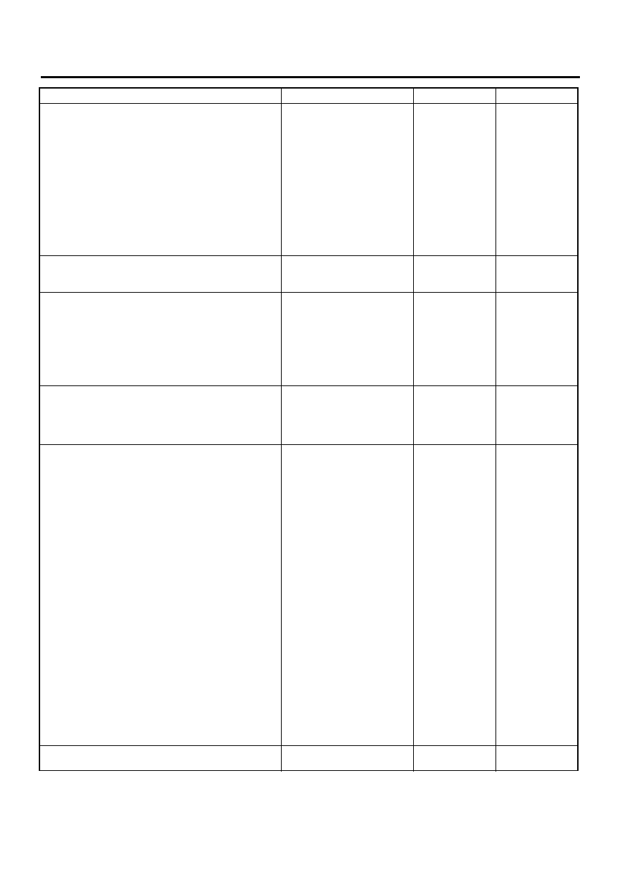
5
CHECK HARNESS/CONNECTOR BETWEEN
VDCCM AND ECM.
1) Turn ignition switch to OFF.
2) Connect connector to ECM.
3) Turn ignition switch to ON.
4) Measure voltage between VDCCM connec-
tor and chassis ground.
Connector & terminal
(F87) No. 21 (+) — Chassis ground (
−−−−
):
(F87) No. 43 (+) — Chassis ground (
−−−−
):
(F87) No. 8 (+) — Chassis ground (
−−−−
):
Is the measured value within the specified
range?
10 — 15 V
6
CHECK POOR CONTACT IN CONNECTORS.
Is there poor contact in connectors between
ECM and VDCCM?
There is poor contact.
Repair connector.
7
CHECK VDCCM.
1) Turn ignition switch to OFF.
2) Connect all connectors.
3) Erase the memory.
4) Perform inspection mode.
5) Read out the diagnostic trouble code.
Is the same diagnostic trouble code as in
the current diagnosis still being output?
Same DTC indicated.
Replace VDCCM.
<Ref. to VDC-8,
VDC Control Mod-
ule (VDCCM).>
8
CHECK ANY OTHER DIAGNOSTIC TROU-
BLE CODES APPEARANCE.
Are other diagnostic trouble codes being out-
put?
Other DTC indicated.
Proceed with the
diagnosis corre-
sponding to the
diagnostic trouble
code.
A temporary poor
contact.
9
CHECK ECM.
1) Turn ignition switch to ON.
2) Measure voltage between ECM connector
terminal and chassis ground.
Connector & terminal
H4 engine RHD without OBD model
(B136) No. 7 (+) — Chassis ground (
−−−−
):
(B136) No. 8 (+) — Chassis ground (
−−−−
):
(B136) No. 2 (+) — Chassis ground (
−−−−
):
H4 engine RHD with OBD model
(B135) No. 6 (+) — Chassis ground (
−−−−
):
(B135) No. 5 (+) — Chassis ground (
−−−−
):
(B135) No. 18 (+) — Chassis ground (
−−−−
):
H4 engine LHD model
(B136) No. 7 (+) — Chassis ground (
−−−−
):
(B136) No. 8 (+) — Chassis ground (
−−−−
):
(B136) No. 2 (+) — Chassis ground (
−−−−
):
H6 engine model
(B134) No. 12 (+) — Chassis ground (
−−−−
):
(B134) No. 4 (+) — Chassis ground (
−−−−
):
(B134) No. 11 (+) — Chassis ground (
−−−−
):
Is the measured value within the specified
range?
10 — 15 V
Repair harness/
connector
between ECM and
VDCCM.
10
CHECK POOR CONTACT IN CONNECTORS.
Is there poor contact in connector ECM?
There is poor contact.
Repair connector.
Step
Value
Yes
No
VDC-81
VDC (DIAGNOSTICS)
DIAGNOSTICS CHART WITH DIAGNOSIS CONNECTOR
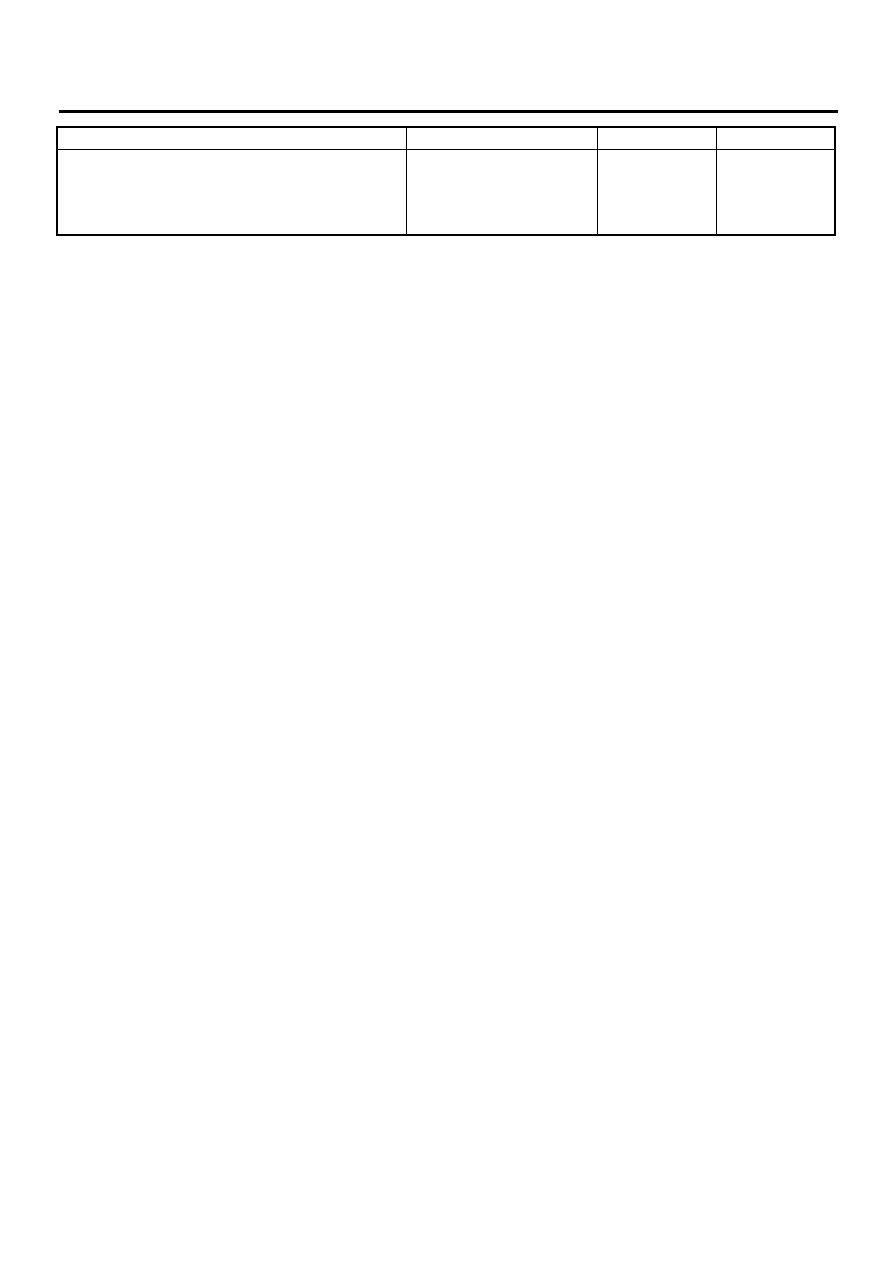
11
CHECK ENGINE.
Is the engine functioning normally?
Operates properly.
Replace ECM.
<Ref. to
FU(H6DO)-46,
Engine Control
Module.>
Repair engine.
Step
Value
Yes
No
VDC-82
VDC (DIAGNOSTICS)
DIAGNOSTICS CHART WITH DIAGNOSIS CONNECTOR
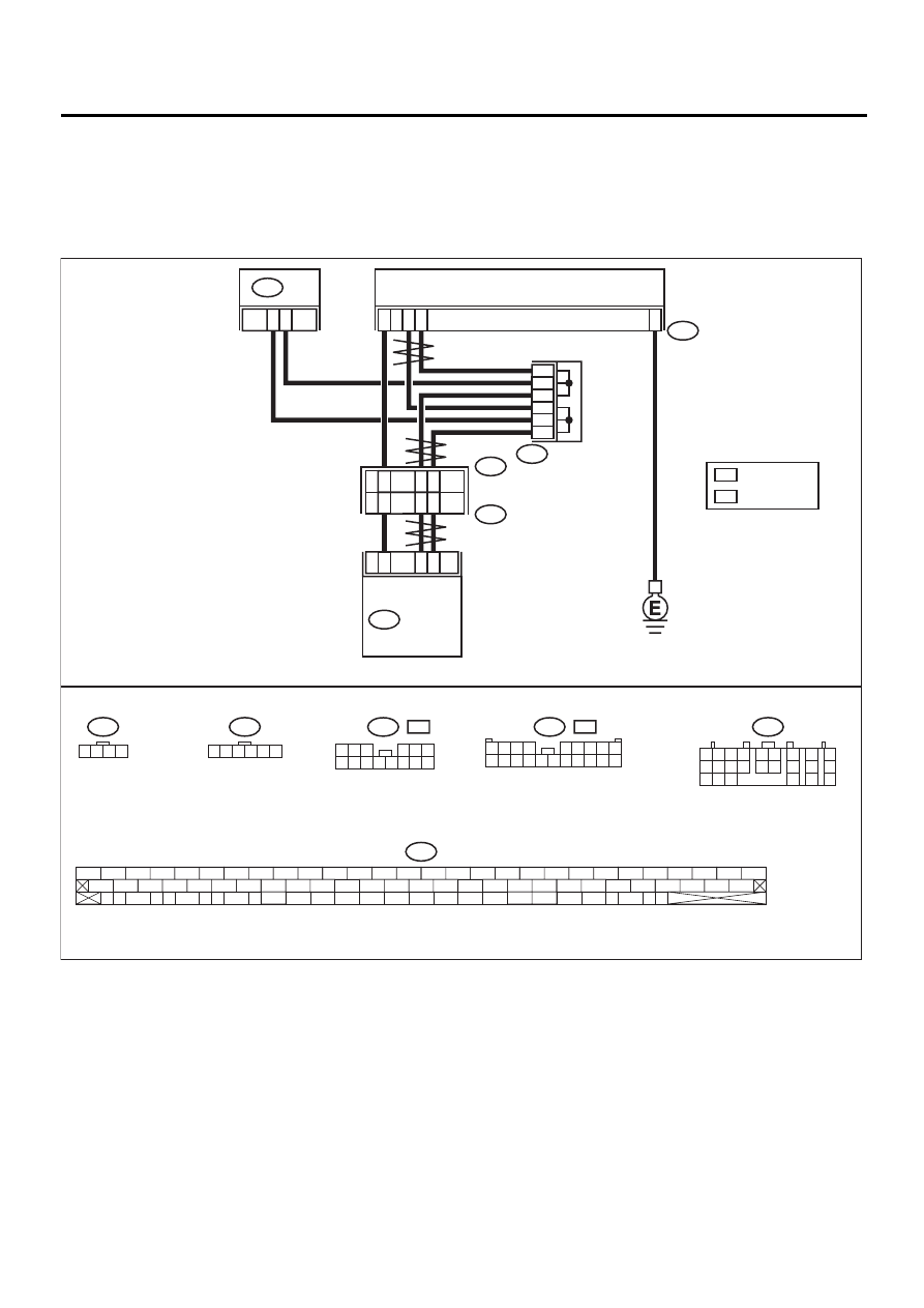
AD:DTC 44 A COMMUNICATION WITH AT CONTROL ABNORMAL
DIAGNOSIS:
• Communication with AT control faults
TROUBLE SYMPTOM:
• VDC does not operate.
WIRING DIAGRAM:
VDC00176
B234
STEERING ANGLE SENSOR
9
18
4
2
1
3
2
3
1
5
6
4
81
27
83
1
15
R
2
5
9
L
6
B231
VDC
CONTROL
MODULE
F96
B225
F87
B56
1 2
7
8
9
5 6
3 4
10 11 12
19 20 21
13
14 15
16
17
18
22
23
24
B231
1 2 3 4
B234
1 2 3 4 5 6
F87
56 57
59 60
62 63
65
82 83
80
27
28
25
26
23
24
21
22
19
20
17
18
15
16
13
14
11
12
9
10
7
8
5
6
3
4
1
2
54
55
52
53
50
51
81
48
49
46
47
44
45
78
79
76
77
75
42
43
40
41
74
72
73
70
71
39
37
38
35
36
69
67
68
66
33
34
61
64
31
32
29
30
58
B56
TCM
1 2 3
4 5 6
7 8 9 10 11 12 13 14
F96
L
:
F96
R
:
R
L
1 2 3 4
5 6 7 8 9
10 11 12 13 14 15 16 17 18 19 20
: RHD MODEL
: LHD MODEL
VDC-83
VDC (DIAGNOSTICS)
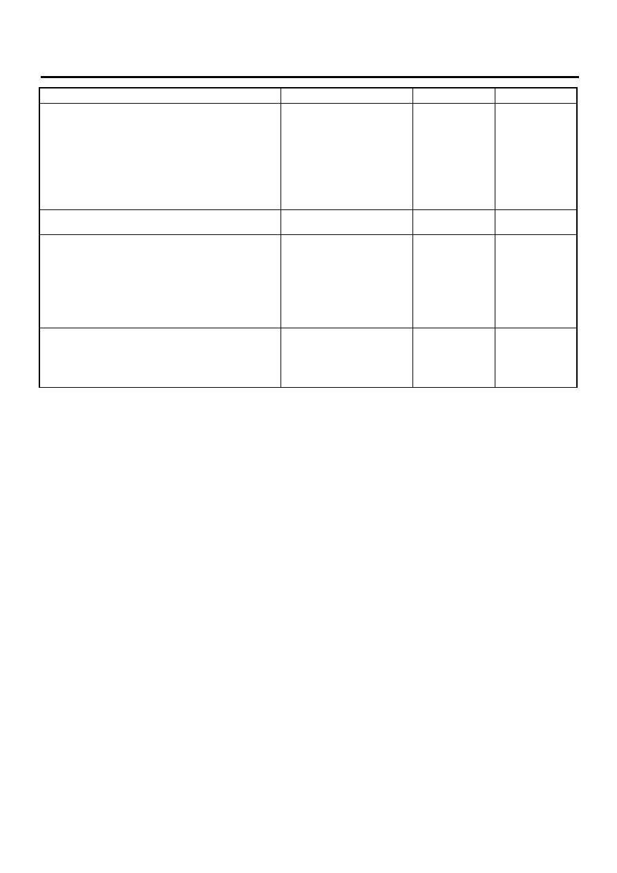
DIAGNOSTICS CHART WITH DIAGNOSIS CONNECTOR
Step
Value
Yes
No
1
CHECK RESISTANCE OF HARNESS.
1) Turn ignition switch to OFF.
2) Disconnect two connectors from TCM.
3) Measure resistance between TCM connec-
tor terminals.
Connector & terminal
(B56) No. 9 — No. 18:
Is the measured value within the specified
range?
57 — 63
Ω
Repair harness
between TCM and
VDCCM.
2
CHECK POOR CONTACT IN CONNECTORS.
Is there poor contact in TCM connectors?
There is poor contact.
Repair connector.
3
CHECK TCM.
1) Turn ignition switch to OFF.
2) Connect all connectors.
3) Erase the memory.
4) Perform inspection mode.
5) Read out the diagnostic trouble code.
Is the same diagnostic trouble code as in
the current diagnosis still being output?
Same DTC indicated.
Replace TCM.
<Ref. to AT-76,
Transmission Con-
trol Module
(TCM).>
4
CHECK ANY OTHER DIAGNOSTIC TROU-
BLE CODES APPEARANCE.
Are other diagnostic trouble codes being out-
put?
Other DTC indicated.
Proceed with the
diagnosis corre-
sponding to the
diagnostic trouble
code.
A temporary poor
contact.
Нет комментариевНе стесняйтесь поделиться с нами вашим ценным мнением.
Текст