Subaru Legacy III (2000-2003 year). Service manual — part 575
AT-34
AUTOMATIC TRANSMISSION (DIAGNOSTICS)
DIAGNOSTIC PROCEDURE FOR POWER INDICATOR LIGHT
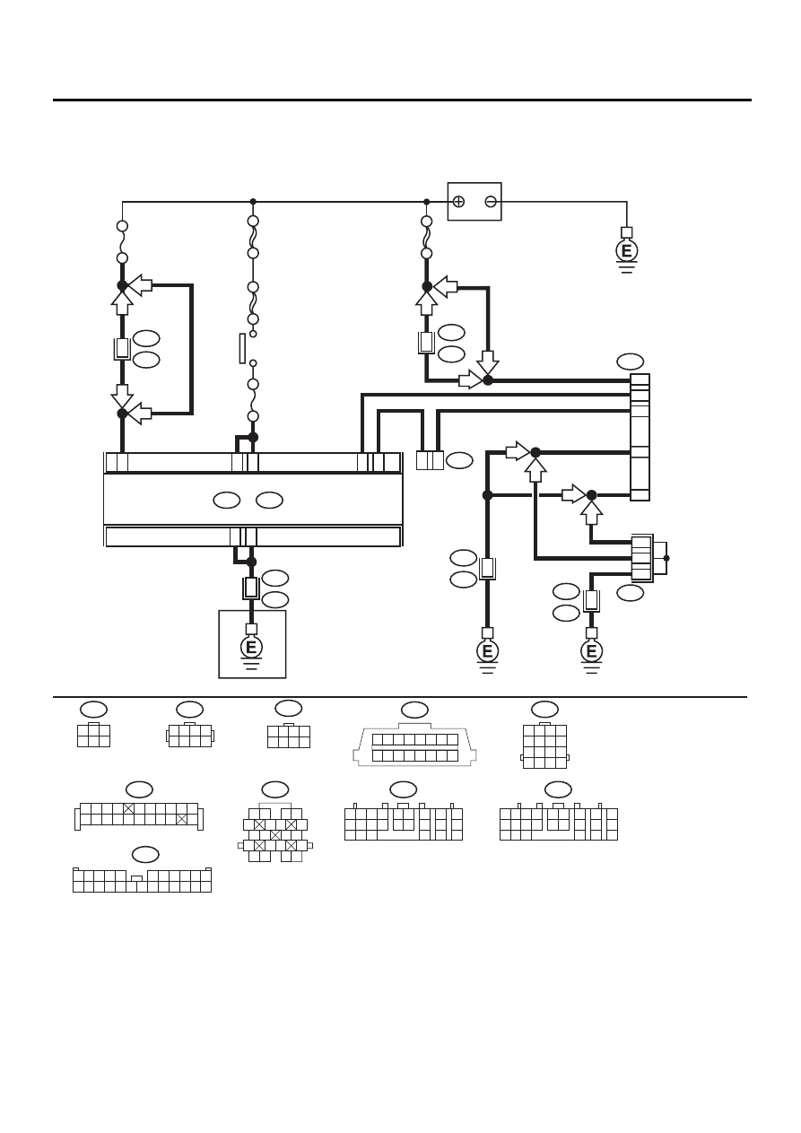
B: CHECK POWER SUPPLY AND GROUND LINE
WIRING DIAGRAM:
AT-00774
C19
A21
C24
C15
4
2
A24
A23
C1
3
NO
. 4
SBF-4
SBF-1
IGNITION
SWITCH
BATTERY
NO
. 11
F44
B61
B22
E3
B83
B252
E49
13
6
10
1
15
16
17
B40
B300
DATA LINK
CONNECTOR
LINE END
CHECK
CONNECTOR
SHIELD AND
SENSOR
GROUND JOINT
CONNECTOR
F2
B100
B11
1 2
5
6 7
8
13
14 15
16
9 10
11 12
3 4
17 18
19 20
B40
1 2 3 4 5 6 7 8
9 10 11 12 13 14 15 16
TCM
B54
A:
B56
C:
B54
1 2
7
8
9
5 6
3 4
10 11 12
19 20 21
13
14 15
16
17
18
22
23
24
B56
1 2
7
8
9
5 6
3 4
10 11 12
19 20 21
13
14 15
16
17
18
22
23
24
LHD
LHD
RHD
RHD
LHD
H4
RHD
LHD
H6
H4
H6
RHD
SBF-5
6
16
2
12
B11
T4
16
TRANSMISSION
1 2 3 4
5 6 7 8
F44
B22
1 2 3 4
5 6 7 8
9 10 11 12
13 14 15 16
B252
1 2 3 4
5 6 7 8
B300
1
3
4 5 6
2
B83
1 2 3 4
5 6 7 8 9 10
11 12
19
20
13 14 15 16 17 18
F2
1
12
9
8
7
6
17
5
4
3
2
14
13
15 16
18
21
20
19
22 23 24
11
10

AT-35
AUTOMATIC TRANSMISSION (DIAGNOSTICS)
DIAGNOSTIC PROCEDURE FOR POWER INDICATOR LIGHT
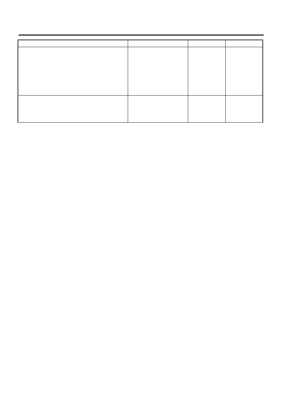
Step
Value
Yes
No
1
CHECK BATTERY TERMINAL.
Turn ignition switch to OFF.
Is there poor contact at battery terminal?
There is poor contact.
Repair battery ter-
minal.
2
CHECK POWER SUPPLY OF TCM.
1) Disconnect connector from TCM.
2) Turn ignition switch to ON.
3) Measure voltage between TCM connector
and chassis ground.
Connector & terminal
(B56) No. 1 (+) — Chassis ground (
−−−−
):
Is the measured value within the specified
range?
10 — 15 V
3
CHECK FUSE (NO. 4).
Remove fuse (No. 4).
Is the fuse (No. 4) blown out?
Fuse is blown.
Replace fuse (No.
4). If replaced fuse
(No. 4) has blown
out easily, repair
short circuit in har-
ness between fuse
(No. 4) and TCM.
Repair open circuit
in harness
between fuse (No.
4) and TCM, or
fuse (No. 4) and
battery, and poor
contact in cou-
pling connector.
4
CHECK IGNITION POWER SUPPLY CIR-
CUIT.
1) Turn ignition switch to ON (engine OFF).
2) Measure ignition power supply voltage
between TCM connector and chassis
ground.
Connector & terminal
(B54) No. 23 (+) — Chassis ground (–):
(B54) No. 24 (+) — Chassis ground (–):
Does the measured value exceed the spec-
ified value?
10 V
5
CHECK FUSE (NO. 11).
Remove fuse (No. 11).
Is the fuse (No. 11) blown out?
Fuse is blown.
Replace fuse (No.
11). If replaced
fuse (No. 11) has
blown out easily,
repair short circuit
in harness
between fuse (No.
11) and TCM.
Repair open circuit
in harness
between fuse (No.
11) and TCM, or
fuse (No. 11) and
battery, and poor
contact in cou-
pling connector.
6
CHECK HARNESS CONNECTOR BETWEEN
TCM AND TRANSMISSION.
1) Turn ignition switch to OFF.
2) Disconnect connector from TCM and trans-
mission.
3) Measure resistance of harness between
TCM and transmission connector.
Connector & terminal
(B56) No. 19 — (B11) No. 16:
(B54) No. 21 — (B11) No. 16:
Is the measured value less than the speci-
fied value?
1
Ω
Repair open circuit
in harness
between TCM and
transmission har-
ness connector,
and poor contact
in coupling con-
nector.
AT-36
AUTOMATIC TRANSMISSION (DIAGNOSTICS)
DIAGNOSTIC PROCEDURE FOR POWER INDICATOR LIGHT
7
CHECK HARNESS CONNECTOR BETWEEN
TRANSMISSION AND TRANSMISSION
GROUND.
Measure resistance of harness between trans-
mission and transmission ground.
Connector & terminal
(T4) No. 16 — Transmission ground:
Is the measured value less than the specified
value?
1
Ω
Repair open circuit
in harness
between transmis-
sion and transmis-
sion ground.
8
CHECK POOR CONTACT IN CONNECTORS.
Is there poor contact in control module power
supply and ground line?
There is poor contact.
Repair connector.
Replace TCM.
<Ref. to AT-76,
Transmission Con-
trol Module
(TCM).>
Step
Value
Yes
No
AT-37
AUTOMATIC TRANSMISSION (DIAGNOSTICS)
DIAGNOSTIC PROCEDURE FOR POWER INDICATOR LIGHT
MEMO:
Нет комментариевНе стесняйтесь поделиться с нами вашим ценным мнением.
Текст