Subaru Legacy III (2000-2003 year). Service manual — part 573
AT-26
AUTOMATIC TRANSMISSION (DIAGNOSTICS)
INSPECTION MODE
8. Inspection Mode
A: OPERATION
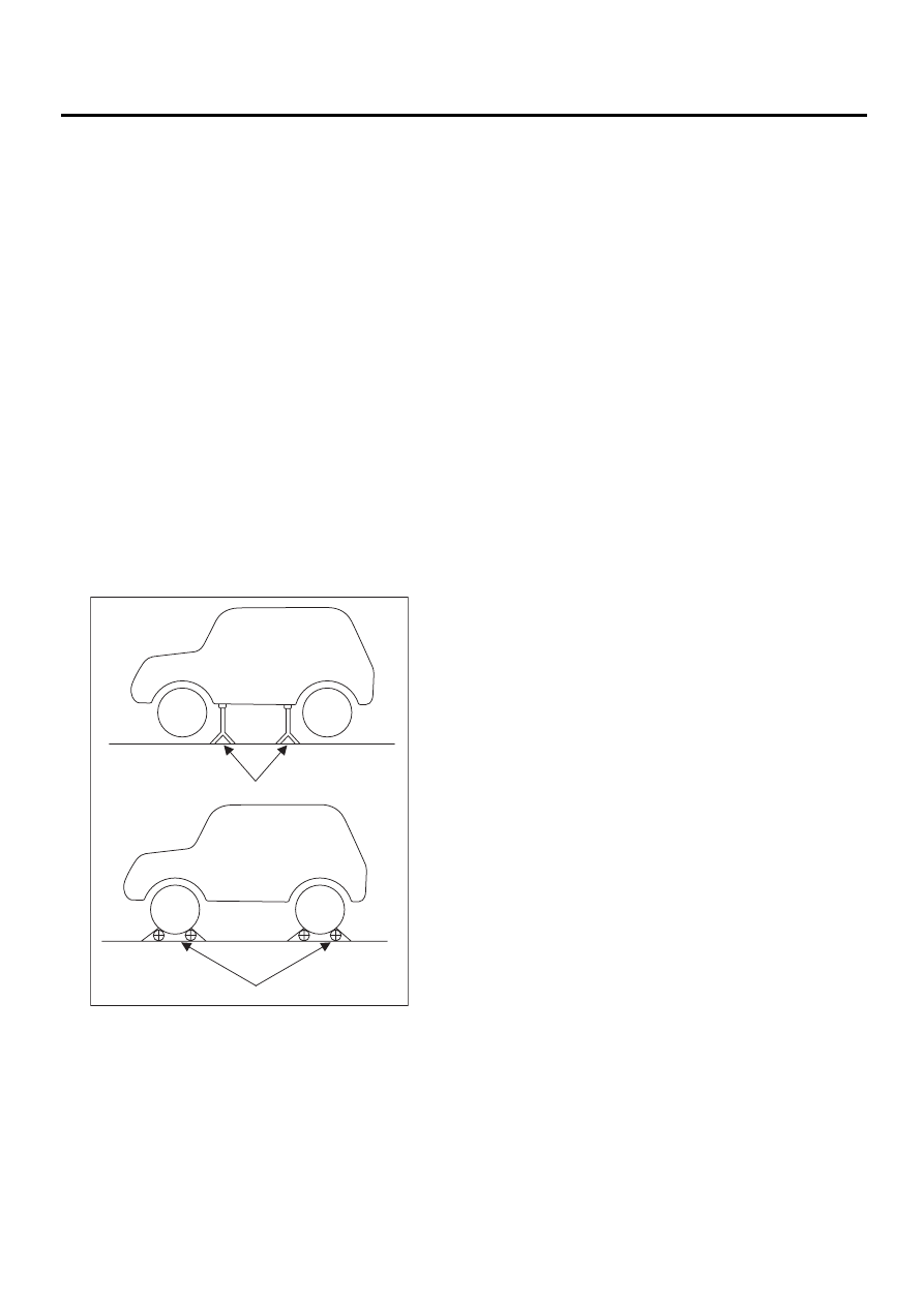
Raise the vehicle using a garage jack and place on
safety stands or drive the vehicle onto free rollers.
WARNING:
• Before raising the vehicle, ensure parking
brakes are applied.
• Do not use a pantograph jack in place of a
safety stand.
• Secure a rope or wire to the front and rear
towing or tie-down hooks to prevent the lateral
runout of front wheels.
• Do not abruptly depress/release clutch pedal
or accelerator pedal during works even when
engine is operating at low speeds since this
may cause vehicle to jump off free rollers.
• In order to prevent the vehicle from slipping
due to vibration, do not place any wooden
blocks or similar items between the safety
stands and the vehicle.
• Since the rear wheels will also rotate, do not
place anything near them. Also, make sure that
nobody goes in front of the vehicle.
(A) Safety stand
(B) Free rollers
AT-00343
( A )
( B )
AT-27
AUTOMATIC TRANSMISSION (DIAGNOSTICS)
CLEAR MEMORY MODE
9. Clear Memory Mode
A: OPERATION
1. WITHOUT SUBARU SELECT MONITOR
Current trouble codes shown on the display are
cleared by turning the ignition switch OFF after
conducting on-board diagnostics operation. Previ-
ous trouble codes, however, cannot be cleared
since they are stored in the TCM memory which is
operating on the back-up power supply. These
trouble codes can be cleared by removing the
specified. Remove TCM connector at least 2 min-
utes.
CLEAR MEMORY:
Remove TCM connector (B56).
• TCM connector is located in the line to the mem-
ory back-up power supply of the TCM. Removal of
this connector clears the previous trouble codes
stored in the TCM memory.
• Be sure to remove TCM connector for at least the
specified length of time. Otherwise, trouble codes
may not be cleared.
2. WITH SUBARU SELECT MONITOR
Refer to Subaru Select Monitor for information
about how to clear trouble codes.
<Ref. to AT-23, CLEAR MEMORY MODE, OPER-
ATION, Subaru Select Monitor.>
AT-28
AUTOMATIC TRANSMISSION (DIAGNOSTICS)
POWER INDICATOR LIGHT DISPLAY
10.POWER Indicator Light Display
A: INSPECTION
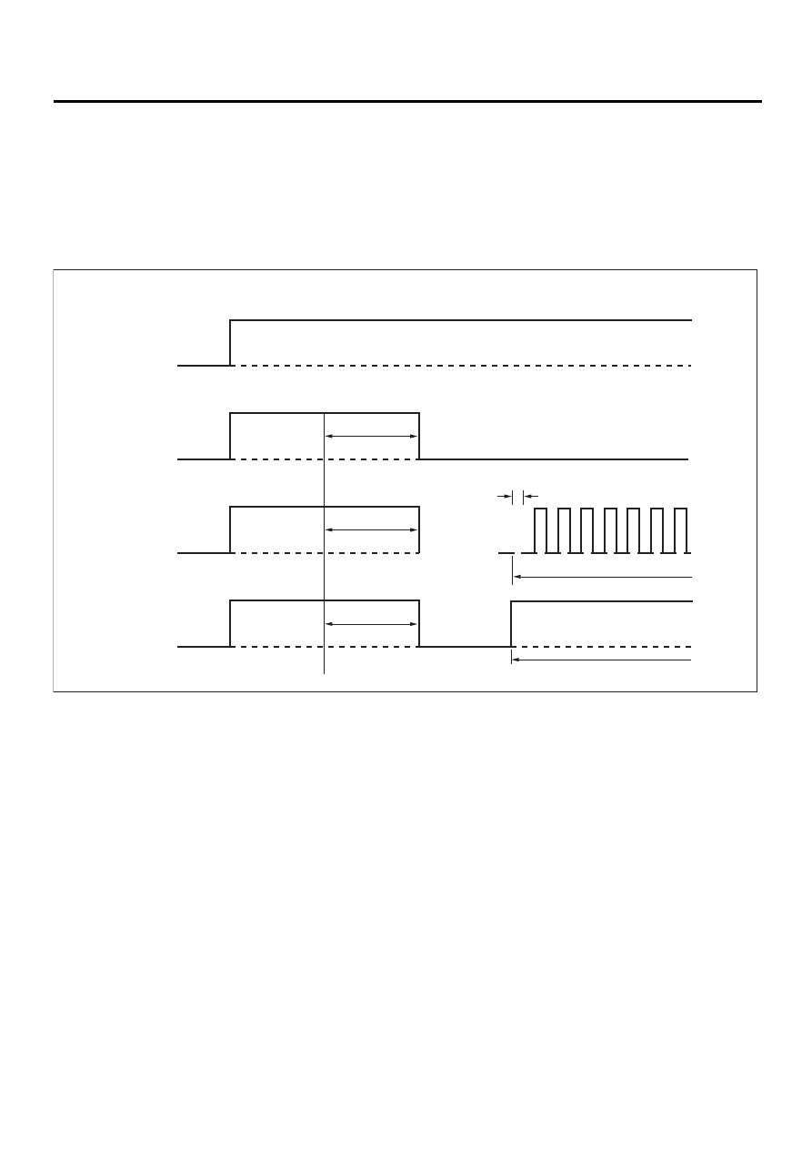
When any on-board diagnostics item is malfunctioning, the display on the POWER indicator light blinks from
the time the malfunction is detected after starting the engine until the ignition switch is turned OFF. The mal-
functioning part or unit can be determined by a DTC during on-board diagnostics operation. Problems which
occurred previously can also be identified through the memory function. If the POWER indicator does not
show a problem (although a problem is occurring), the problem can be determined by checking the perfor-
mance characteristics of each sensor using the select monitor. Indicator signal is as shown in the figure.
AT-00344
2 secs
2 secs
2 secs
• Ignition switch (engine OFF)
ON
ON
ON
ON
OFF
OFF
OFF
OFF
• Normal
• Abnormal (Trouble occurs.)
• Normal (power switch ON)
0.25 secs
Blink
Power indicator light ON

AT-29
AUTOMATIC TRANSMISSION (DIAGNOSTICS)
LIST OF DIAGNOSTIC TROUBLE CODE (DTC)
11.List of Diagnostic Trouble Code (DTC)
A: LIST
DTC No.
Item
Content of diagnosis
Index
11
Engine speed signal
Detects open or shorted
input signal circuit.
23
Mass air flow signal
(TURBO model)
Detects open or shorted
output signal circuit.
27
ATF temperature sensor
Detects open or shorted
input signal circuit.
31
Throttle position sensor
Detects open or shorted
input signal circuit.
33
Front vehicle speed sensor
Detects open or shorted
input signal circuit.
36
Torque converter turbine
speed sensor
Detects open or shorted
input signal circuit.
38
Torque control signal
Detects open or shorted
input signal circuit.
45
Intake manifold pressure
signal (Non-TURBO model)
Detects open or shorted
input signal circuit.
71
Shift solenoid 1
Detects open or shorted
output signal circuit.
<Ref. to AT-72, DTC 71 SHIFT SOLENOID 1, Diagnostic
Procedure with Diagnostic Trouble Code (DTC).>
72
Shift solenoid 2
Detects open or shorted
output signal circuit.
<Ref. to AT-76, DTC 72 SHIFT SOLENOID 2, Diagnostic
Procedure with Diagnostic Trouble Code (DTC).>
73
Low clutch timing solenoid
Detects open or shorted
output signal circuit.
74
2-4 brake timing solenoid
Detects open or shorted
output signal circuit.
75
Line pressure duty solenoid
Detects open or shorted
output signal circuit.
76
2-4 brake duty solenoid
Detects open or shorted
output signal circuit.
77
Lock-up duty solenoid
Detects open or shorted
output signal circuit.
78
SPORT shift solenoid
Detects open or shorted
output signal circuit.
79
Transfer duty solenoid
Detects open or shorted
output signal circuit.
86
VDC communication signal
Detects open or shorted
input signal circuit.
93
Rear vehicle speed sensor
Detects open or shorted
input signal circuit.
Нет комментариевНе стесняйтесь поделиться с нами вашим ценным мнением.
Текст