Subaru Legacy III (2000-2003 year). Service manual — part 574
AT-30
AUTOMATIC TRANSMISSION (DIAGNOSTICS)
DIAGNOSTIC PROCEDURE FOR POWER INDICATOR LIGHT
12.Diagnostic Procedure for POWER Indicator Light
A: POWER INDICATOR LIGHT DOES NOT COME ON OR GO OFF
DIAGNOSIS:
The POWER Indicator light circuit is open or shorted.
TROUBLE SYMPTOM:
• When ignition switch is turned to ON (engine OFF), POWER indicator light does not illuminate.
• When on-board diagnostics is performed, POWER indicator light remains illuminated.
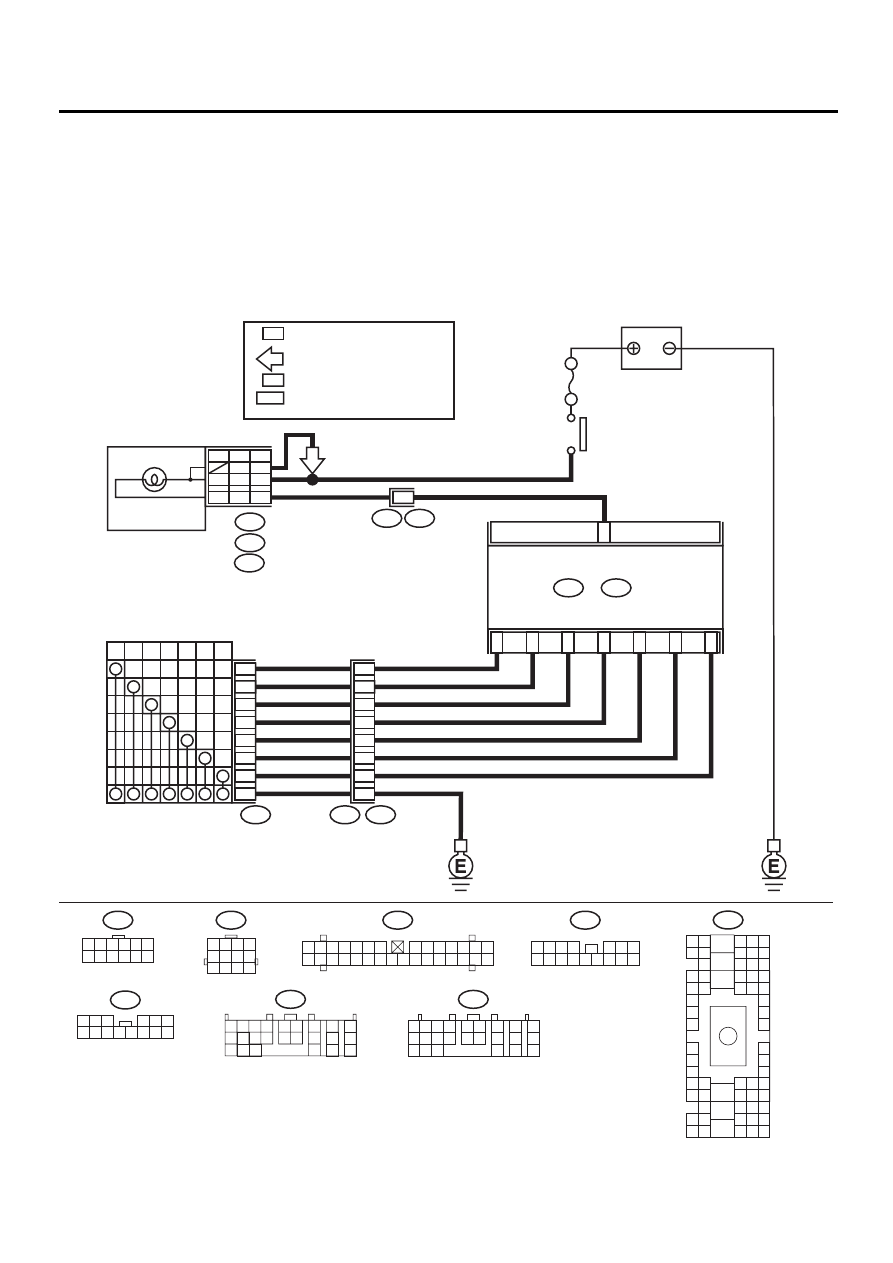
WIRING DIAGRAM:
AT-00773
9
INHIBITOR SWITCH
COMBINATION
METER
8
10
3
11
4
6
5
P
R
N
D
3
2
1
3
2
1
8
7
6
5
4
B7
B6
B5
B4
B14
B3
B1
T7
T3
B12
C11
i10
A:
i11
B:
i12
C:
i1
B36
NO. 5
BATTERY
IGNITION
RELAY
T7
B12
1 2 3 4
5 6 7 8
9 10 11 12
i12
1 2 3
4 5 6
7 8 9 10 11 12 13 14
TCM
B55
B:
B56
C:
1 2 3 4 5 6
7 8 9 10 11 12
B55
1 2 3 4
10 11 12
19 20 21
13
5 6
14 15
7
8
9
16
17
18
22
23
24
B56
1 2
7
8
9
5 6
3 4
10 11 12
19 20 21
13
14 15
16
17
18
22
23
24
A13
B12
H6RT
H6L
B5
A8
B5
B6
H4N
C3
A8
P5
POWER
H6RT
H4N : LHD 3.0L MODEL
: RHD 3.0L MODEL AND
TURBO MODEL
H4N : EXCEPT 3.0L MODEL AND
NON-TURBO MODEL
: 3.0L MODEL AND TURBO MODEL
i11
1 2 3
8 9 10
4
11 12 13 14 15 16
5 6 7
B36
B4 B5 B6
A4 A5 A6
C5 C6
F6
D4 D5 D6
F1
H1
C4
G6
G1
C2
K1
M1 M2
K6
L1
D1 D2
A1 A2
B1 B2
I6
J6
L2
I1
J1
H6
M4 M5 M6
L4 L5 L6
N5 N6
O4 O5 O6
N4
P4 P5
N2
O1 O2
P1 P2
N3
O3
P3
P6
A3
B3
C3
E4 E5 E6
E1 E2
H6
H6
i10
1 2 3 4 5 6 7
8 9 10 11 12 13 14
15 16 17 18 19 20 21 22 23 24 25 26 27 28 29 30

AT-31
AUTOMATIC TRANSMISSION (DIAGNOSTICS)
DIAGNOSTIC PROCEDURE FOR POWER INDICATOR LIGHT
Step
Value
Yes
No
1
CHECK POWER INDICATOR LIGHT.
Turn ignition switch to ON (engine OFF).
Does POWER indicator light illuminate?
POWER indicator illuminates.
2
CHECK POWER INDICATOR LIGHT.
1) Turn ignition switch to OFF.
2) Remove combination meter.
3) Remove POWER indicator light bulb from
combination meter.
Is POWER indicator light bulb OK?
Bulb is normal.
Replace POWER
indicator light bulb.
3
CHECK POWER INDICATOR LIGHT.
Perform “Read Diagnostic Trouble Code
(DTC)”. <Ref. to AT-24, WITHOUT SUBARU
SELECT MONITOR, OPERATION, Read
Diagnostic Trouble Code (DTC).>
Does POWER indicator light blink?
Power indicator light illumi-
nates.
A temporary poor
contact of the con-
nector or harness
may be the cause.
Repair harness or
connector in TCM,
inhibitor switch
and combination
meter.
4
CHECK FUSE (No. 5).
Remove fuse (No. 5).
Is the fuse (No. 5) blown out?
Fuse is blown.
Replace fuse (No.
5). If replaced fuse
(No. 5) is blown
out easily, repair
short circuit in har-
ness between fuse
(No. 5) and combi-
nation meter.
5
CHECK HARNESS CONNECTOR BETWEEN
COMBINATION METER AND IGNITION RE-
LAY.
1) Turn ignition switch to ON (engine OFF).
2) Measure voltage between combination
meter connector and chassis ground.
Connector & terminal
Except 3.0 L model
(i12) No. 3 (+) — Chassis ground (
−−−−
):
3.0 L model
(i11) No. 5 (+) — Chassis ground (
−−−−
):
(i10) No. 8 (+) — Chassis ground (
−−−−
):
Does the measured value exceed the spec-
ified value?
9 V
Repair open or
short circuit in har-
ness between
combination meter
and battery.
6
CHECK COMBINATION METER.
Measure voltage between combination meter
connector and chassis ground.
Connector & terminal
Except 3.0 L model and TURBO model
(i11) No. 6 (+) — Chassis ground (
−−−−
):
LHD: 3.0 L model
(i11) No. 12 (+) — Chassis ground (
−−−−
):
RHD: 3.0 L model and TURBO model
(i10) No. 13 (+) — Chassis ground (
−−−−
):
Is the measured value less than the specified
value?
1 V
Repair combina-
tion meter. <Ref.
to IDI-14, Combi-
nation Meter
Assembly.>

AT-32
AUTOMATIC TRANSMISSION (DIAGNOSTICS)
DIAGNOSTIC PROCEDURE FOR POWER INDICATOR LIGHT
7
CHECK OPEN CIRCUIT OF HARNESS.
1) Turn ignition switch to OFF.
2) Disconnect TCM and combination meter
connector.
3) Measure resistance of harness between
combination meter.
Connector & terminal
Except 3.0 L model and TURBO model
(B56) No. 11 — (i11) No. 6:
LHD: 3.0 L model
(B56) No. 11 — (i12) No. 12
RHD: 3.0 L and TURBO models
(B56) No. 11 — (i0) No. 13
Is the measured value less than the speci-
fied value?
1
Ω
Repair open circuit
in harness
between TCM and
combination
meter, and poor
contact in cou-
pling connector.
8
CHECK INPUT SIGNAL FOR TCM.
1) Connect connector to TCM and combina-
tion meter.
2) Turn ignition switch to ON (engine OFF).
3) Measure voltage between TCM connector
and chassis ground.
Connector & terminal
(B56) No. 11 (+) — Chassis ground (
−−−−
):
Is the measured value less than the speci-
fied value?
1 V
Even if POWER
indicator lights up,
the circuit has
returned to a nor-
mal condition at
this time. A tempo-
rary poor contact
of the connector or
harness may be
the cause. Repair
harness or con-
nector in TCM.
Replace TCM.
<Ref. to AT-76,
Transmission Con-
trol Module
(TCM).>
9
CHECK SUBARU SELECT MONITOR.
Do you have Subaru Select Monitor?
Subaru Select Monitor is avail-
able.
10
CHECK INHIBITOR SWITCH.
1) Connect Subaru Select Monitor to data link
connector.
2) Turn ignition switch to ON.
3) Subaru Select Monitor to ON.
4) Read data of range switch using Subaru
Select Monitor.
•Range switch is indicated in ON
⇔
OFF.
When each range is selected, does LED of
Subaru Select Monitor light up?
LED lights up.
Check inhibitor
switch circuit.
<Ref. to AT-132,
CHECK INHIBI-
TOR SWITCH.,
Diagnostic Proce-
dure for No-diag-
nostic Trouble
Code (DTC).>
11
CHECK SHORT CIRCUIT OF HARNESS.
1) Disconnect connector from TCM.
2) Remove combination meter.
3) Disconnect connector from combination
meter.
4) Measure resistance of harness connector
between TCM and chassis ground.
Connector & terminal
(B56) No. 11 (+) — Chassis ground (
−−−−
):
Is the measured value less than the speci-
fied value?
1 M
Ω
Replace TCM.
<Ref. to AT-76,
Transmission Con-
trol Module
(TCM).>
Repair short circuit
in harness
between combina-
tion meter connec-
tor and TCM
connector.
Step
Value
Yes
No
AT-33
AUTOMATIC TRANSMISSION (DIAGNOSTICS)
DIAGNOSTIC PROCEDURE FOR POWER INDICATOR LIGHT
MEMO:
Нет комментариевНе стесняйтесь поделиться с нами вашим ценным мнением.
Текст