Subaru Legacy III (2000-2003 year). Service manual — part 576
AT-38
AUTOMATIC TRANSMISSION (DIAGNOSTICS)
DIAGNOSTIC PROCEDURE FOR SELECT MONITOR COMMUNICATION
13.Diagnostic Procedure for Select Monitor Communication
A: COMMUNICATION FOR INITIALIZING IMPOSSIBLE
DIAGNOSIS:
• Faulty harness connector
TROUBLE SYMPTOM:
• Select monitor communication failure
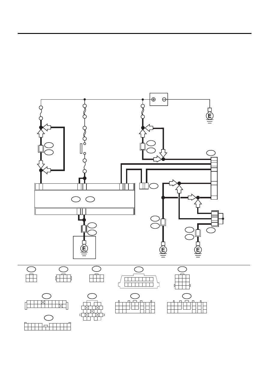
WIRING DIAGRAM:
AT-00774
C19
A21
C24
C15
4
2
A24
A23
C1
3
N
O. 4
SBF-4
SBF-1
IGNITION
SWITCH
BATTERY
NO
. 11
F44
B61
B22
E3
B83
B252
E49
13
6
10
1
15
16
17
B40
B300
DATA LINK
CONNECTOR
LINE END
CHECK
CONNECTOR
SHIELD AND
SENSOR
GROUND JOINT
CONNECTOR
F2
B100
B11
1 2
5
6 7
8
13
14 15
16
9 10
11 12
3 4
17 18
19 20
B40
1 2 3 4 5 6 7 8
9 10 11 12 13 14 15 16
TCM
B54
A:
B56
C:
B54
1 2
7
8
9
5 6
3 4
10 11 12
19 20 21
13
14 15
16
17
18
22
23
24
B56
1 2
7
8
9
5 6
3 4
10 11 12
19 20 21
13
14 15
16
17
18
22
23
24
LHD
LHD
RHD
RHD
LHD
H4
RHD
LHD
H6
H4
H6
RHD
SBF-5
6
16
2
12
B11
T4
16
TRANSMISSION
1 2 3 4
5 6 7 8
F44
B22
1 2 3 4
5 6 7 8
9 10 11 12
13 14 15 16
B252
1 2 3 4
5 6 7 8
B300
1
3
4 5 6
2
B83
1 2 3 4
5 6 7 8 9 10
11 12
19
20
13 14 15 16 17 18
F2
1
12
9
8
7
6
17
5
4
3
2
14
13
15 16
18
21
20
19
22 23 24
11
10

AT-39
AUTOMATIC TRANSMISSION (DIAGNOSTICS)
DIAGNOSTIC PROCEDURE FOR SELECT MONITOR COMMUNICATION
Step
Value
Yes
No
1
CHECK SUBARU SELECT MONITOR POW-
ER SUPPLY CIRCUIT.
Measure voltage between data link connector
and chassis ground.
Connector & terminal
(B40) No. 1 (+) — Chassis ground (
−−−−
):
Does the measured value exceed the specified
value?
10 V
Repair harness
and connector
between battery
and data link con-
nector, and poor
contact in cou-
pling connector.
2
CHECK SUBARU SELECT MONITOR
GROUND CIRCUIT.
Measure resistance of harness between data
link connector and chassis ground.
Connector & terminal
(B40) No. 12 — Chassis ground:
(B40) No. 13 — Chassis ground:
Is the measured value less than the specified
value?
1
Ω
Repair open circuit
in harness
between data link
connector and
ground terminal,
and poor contact
in coupling con-
nector.
3
CHECK COMMUNICATION OF SELECT
MONITOR.
1) Turn ignition switch to ON.
2) Using the select monitor, check whether
communication to engine systems can be
executed normally.
Are the name and year of the system dis-
played on the select monitor?
Name and year are displayed. Go to step 6.
4
CHECK COMMUNICATION OF SELECT
MONITOR.
1) Turn ignition switch to OFF.
2) Disconnect TCM connector.
3) Check whether communication to engine
systems can be executed normally.
Are the name and year of the system dis-
played on the select monitor?
Name and year are displayed. Go to step 8.
5
CHECK COMMUNICATION OF SELECT
MONITOR.
1) Turn ignition switch to OFF.
2) Connect TCM connector.
3) Disconnect ECM connector.
4) Check whether communication to transmis-
sion systems can be executed normally.
Are the name and year of the system dis-
played on the select monitor?
Name and year are displayed. Inspect ECM.
6
CHECK HARNESS CONNECTOR BETWEEN
EACH CONTROL MODULE AND DATA LINK
CONNECTOR.
1) Turn ignition switch to OFF.
2) Disconnect TCM and ECM connectors.
3) Measure resistance between data link con-
nector and chassis ground.
Connector & terminal
(B40) No. 10 — Chassis ground:
(B40) No. 6 — Chassis ground:
Does the measured value exceed the spec-
ified value?
1 M
Ω
Repair harness
and connector
between each
control module
and data link con-
nector.

AT-40
AUTOMATIC TRANSMISSION (DIAGNOSTICS)
DIAGNOSTIC PROCEDURE FOR SELECT MONITOR COMMUNICATION
7
CHECK OUTPUT SIGNAL FOR TCM.
1) Turn ignition switch to ON.
2) Measure voltage between data link connec-
tor and chassis ground.
Connector & terminal
(B40) No. 10 (+) — Chassis ground (
−−−−
):
(B40) No. 6 (+) — Chassis ground (
−−−−
):
Does the measured value exceed the spec-
ified value?
1 V
Repair harness
and connector
between each
control module
and data link con-
nector.
A temporary poor
contact of the con-
nector or harness
may be the cause.
Repair harness or
connector in the
circuit.
8
CHECK HARNESS/CONNECTOR BETWEEN
TCM AND DATA LINK CONNECTOR.
Measure resistance between TCM connector
and data link connector.
Connector & terminal
(B56) No. 15 — (B40) No. 10:
Is the measured value less than the specified
value?
0.5
Ω
Repair harness
and connector
between TCM and
data link connec-
tor.
9
CHECK HARNESS/CONNECTOR BETWEEN
TCM AND DATA LINK CONNECTOR.
Measure resistance between TCM connector
and data link connector.
Connector & terminal
(B56) No. 24 — (B40) No. 6:
Does the measured value exceed the specified
value?
1 M
Ω
Repair harness
and connector
between TCM and
data link connec-
tor.
10
CHECK INSTALLATION OF TCM CONNEC-
TOR.
Turn ignition switch to OFF.
Is TCM connector inserted into TCM?
TCM connector is inserted cor-
rectly.
Insert TCM con-
nector into TCM.
11
CHECK POOR CONTACT IN CONNECTORS.
Is there poor contact in control module and
data link connector?
There is poor contact.
Repair poor con-
tact.
Replace TCM.
<Ref. to AT-76,
Transmission Con-
trol Module
(TCM).>
Step
Value
Yes
No
AT-41
AUTOMATIC TRANSMISSION (DIAGNOSTICS)
DIAGNOSTIC PROCEDURE FOR SELECT MONITOR COMMUNICATION
MEMO:
Нет комментариевНе стесняйтесь поделиться с нами вашим ценным мнением.
Текст