Subaru Legacy III (2000-2003 year). Service manual — part 550
AT-94
AUTOMATIC TRANSMISSION
TRANSFER CLUTCH
E: INSPECTION
• Check the drive plate facing for wear and dam-
age.
• Check the snap ring for wear, return spring for
permanent set and breakage, and return spring for
deformation.
• Check the D-ring for damage.
• Measure the extension end play and adjust it to
within specifications.
<Ref. to AT-94, ADJUSTMENT, Transfer Clutch.>
1) Inspect clearance between snap ring and pres-
sure plate.
2) Before measuring clearance, place the same
thickness of shim on both sides to prevent pressure
plate from tilting.
3) If the clearance is not within specification, adjust
it by selecting a suitable pressure plate on the
transfer clutch piston side.
Standard value:
0.7 — 1.1 mm (0.028 — 0.043 in)
Allowable limit:
1.6 mm (0.063 in)
4) Check if the tight corner braking does not occur
when the vehicle is started with steering wheel held
at fully turned position. If tight corner braking oc-
curs, perform the following procedures.
(1) With the steering wheel held at fully turned
position, drive the vehicle in “D” range and with
vehicle speed at approx. 5 km/h (3 MPH) in both
clockwise and counterclockwise directions for
approx. ten times each, while repeating acceler-
ation and braking intermittently.
(2) If the tight corner braking still persists, drive
the vehicle again in a circle for several laps.
F: ADJUSTMENT
1. MPT MODEL
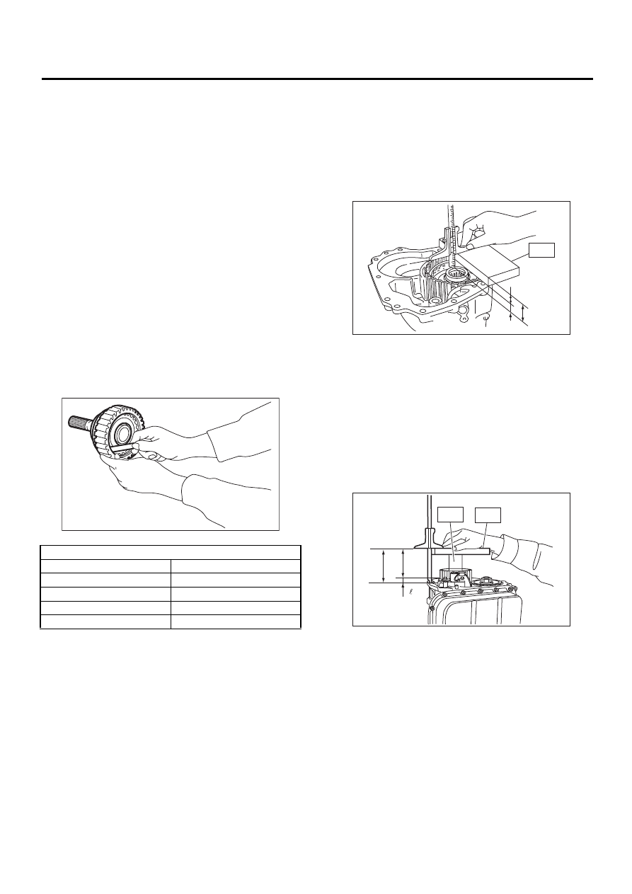
1) Measure distance “L” from end of extension
case and rear drive shaft with ST.
ST
398643600
GAUGE
L = Measured value
−
15 mm
(L = Measured value
−
0.59 in)
A:
Measured value
B:
ST thickness [15 mm (0.59 in)]
L:
Distance from end of extension case to end of
rear drive shaft
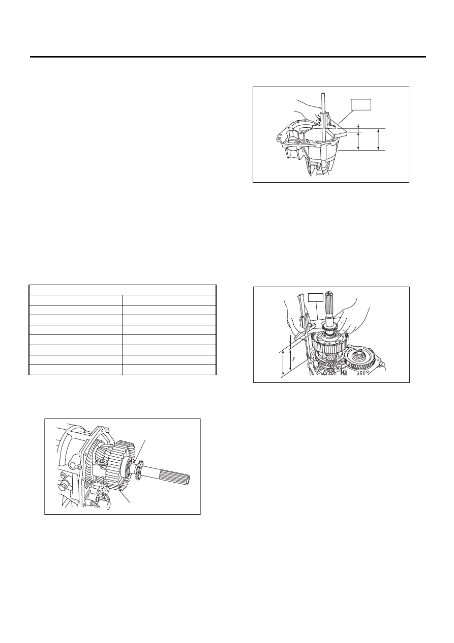
2) Measure the distance “
2
” from the transmission
case mating surface to the reduction drive gear end
surface with ST1 and ST2.
2
= Measured value
−
50 mm
(
2
= Measured value
−
1.97 in)
ST1
398643600
GAUGE
ST2
499577000
GAUGE
A:
Measured value
B:
ST thickness [50 mm (1.97 in)]
2
:
Distance from end of transmission case to
end of reduction drive gear
3) Calculation equation:
NOTE:
Calculate “H”:
When clearance is at 0.05 mm (0.0020 in) and 0.25
mm (0.0098 in), then select a suitable thrust needle
bearing from the table.
H = (L + 0.45 mm)
−
2
−
T
[H = (L + 0.0177 in)
−
2
−
T]
T:
Thrust needle bearing thickness
Available pressure plates
Part No.
Thickness mm (in)
31593AA151
3.3 (0.130)
31593AA161
3.7 (0.146)
31593AA171
4.1 (0.161)
31593AA181
4.5 (0.177)
AT-00142
A
B
L
ST
AT-00143
ST2
ST1
A
B
AT-00144
AT-95
AUTOMATIC TRANSMISSION
TRANSFER CLUTCH
L:
Distance from end of extension case to end of
rear drive shaft
0.45 mm (0.0177 in):
Gasket thickness
2
:
Distance from end of transmission case to
end of reduction drive gear
H:
Shim clearance
0.05 — 0.25 mm (0.0020 — 0.0098 in)
Example:
When, L = 18.60 mm (0.7323 in),
2
= 15.05 mm
(0.5925 in)
Calculation when clearance is 0.05 mm
(0.0020 in)
H = (18.60 + 0.45)
−
15.05
−
0.05 = 3.95
[H = (0.7323 + 0.0177)
−
0.5925
−
0.0020 =
0.1555]
Calculation when clearance is 0.25 mm
(0.0098 in)
H = (18.60 + 0.45)
−
15.05
−
0.25 = 3.75
[H = (0.7323 + 0.0177)
−
0.5925
−
0.0098 =
0.1476]
After calculation, the value of “H” becomes be-
tween 3.75 and 3.95, therefore select bearing thick-
ness of 3.8.
2. VTD MODEL
1) Insert the rear driveshaft into the reduction drive
gear and center differential assembly.
2) Using the special tool, measure the distance "L"
between the mating surface of extension case and
multi-plate clutch (LSD) piston.
ST
398643600
GAUGE
L = Measured value
−
15 mm
(L = Measured value
−
0.59 in)
A:
Measured value
B:
Thickness of special tool [15 mm (0.59 in)]
L:
Distance between extension case edge and
rear driveshaft edge
3) Using the special tool, measure the distance “
2
”
between the mating surface of transmission case
and reduction drive gear edge.
2
= Measured value
−
15 mm
(
2
= Measured value
−
0.59 in)
ST
398643600
GAUGE
A:
Measured value
B:
Thickness of special tool [15 mm (0.59 in)]
2
:
Distance between extension case edge and
reduction drive gear edge
4) Formula:
NOTE:
Calculation of “H”:
When clearances are 0.05 mm (0.0020 in) and 0.25
mm (0.0098 in), select up to four adjusting shims
from the table, suitable for clearance value.
H = (L + 0.45 mm)
−
2
−
T
[H = (L + 0.0177 in)
−
2
−
T]
T:
Shim clearance
L:
Distance between extension case edge and
rear driveshaft edge
0.45 mm (0.0177 in):
Gasket thickness
2
:
Distance between transmission case edge
and reduction drive gear edge
T:
Shim thickness
0.05 — 0.25 mm (0.0020 — 0.0098 in)
Example:
Thrust needle bearing
Part No.
Thickness mm (in)
806536020
3.8 (0.150)
806535030
4.0 (0.157)
806535040
4.2 (0.165)
806535050
4.4 (0.173)
806535060
4.6 (0.181)
806535070
4.8 (0.189)
806535090
5.0 (0.197)
(A) Rear drive plate
(B) Center differential carrier
( A )
( B )
AT-00145
ST1
B
L
A
AT-00146
A
B
ST
AT-00147

AT-96
AUTOMATIC TRANSMISSION
TRANSFER CLUTCH
When, L = 90.50 mm (3.5630 in),
2
= 90.35 mm
(3.5571 in)
Calculation for 0.05 mm of clearance (0.0020 in)
H = (90.50 + 0.45)
−
90.35
−
0.05 = 0.55
[H = (3.5630 + 0.0177)
−
3.5571
−
0.0020 =
0.0217]
Calculation when clearance is 0.25 mm
(0.0098 in)
H = (90.50 + 0.45)
−
90.35
−
0.25 = 0.35
[H = (3.5630 + 0.0177)
−
3.5571
−
0.0098 =
0.0138]
After calculation, the value of “H” becomes be-
tween 0.35 mm (0.0138 in) and 0.55 mm (0.0216
in), therefore select two shims with thickness of 0.2
mm (0.010 in) or one shim with thickness of 0.5 mm
(0.020 in).
Adjusting shim
Part No.
Thickness mm (in)
33281AA001
0.2 (0.008)
33281AA011
0.5 (0.020)
AT-97
AUTOMATIC TRANSMISSION
MULTI-PLATE CLUTCH
27.Multi-plate Clutch
A: REMOVAL
Remove multi-plate clutch following the same in-
structions as for the extension case. <Ref. to AT-
86, REMOVAL, Extension Case.>
B: INSTALLATION
Install multi-plate clutch following the same instruc-
tions as for the extension case. <Ref. to AT-86, IN-
STALLATION, Extension Case.>
C: INSPECTION
• Inspect drive plate facing for wear and damage.
• Make sure snap ring is not worn and return
spring has no permanent distortion, damage, or de-
formation.
• Inspect D-ring for damage.
• Measure multi-plate clutch clearance and adjust
it to within the specification range. <Ref. to AT-97,
ADJUSTMENT, Multi-plate Clutch.>
D: ADJUSTMENT
1) Remove drive plate and driven plate from center
differential carrier.
2) Using the special tool, measure distance “L”
from extension case joining surface to multi-plate
clutch (LSD) piston.
ST
398643600
Gauge
L = Measured value
−
15 mm
(L = Measured value
−
0.59 in)
A:
Measured value
B:
Special tool thickness [15 mm (0.59 in)]
L:
Distance from the extension case edge to the
rear driveshaft edge.
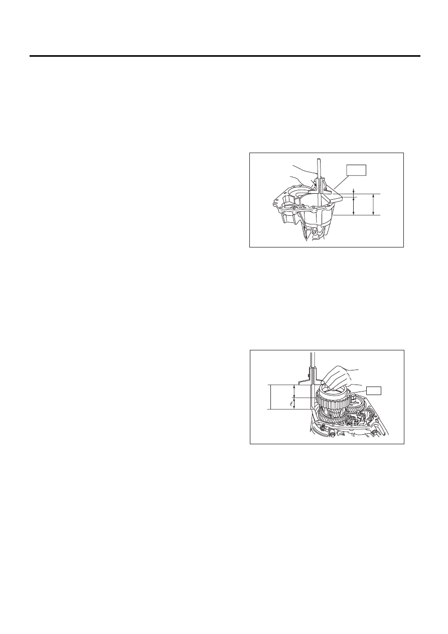
3) Using ST, measure height “
2
” from transmis-
sion case joining edge to center differential clutch
drum edge.
ST
398744300
GAUGE
2
= Measurement value
−
50 mm
(
2
= Measurement value
−
1.97 in)
A:
Measurement value
B:
Special tool thickness [50 mm (1.97 in)]
2
:
Measure distance from transmission case
joining surface to multi-plate clutch (LSD) piston.
4) Calculation formula
T = (L + 0.45 mm)
−
2
[T = (L + 0.0177 in)
−
2
]
T:
Measurement value between clutch drum and
multi-plate clutch (LSD) piston
L:
Distance from extension case joining surface
to multi-plate clutch (LSD) piston
0.45:
Gasket thickness
2
:
Distance from transmission case joining sur-
face to center differential clutch drum edge
ST1
B
L
A
AT-00146
A
B
ST
AT-00148
Нет комментариевНе стесняйтесь поделиться с нами вашим ценным мнением.
Текст