Subaru Legacy III (2000-2003 year). Service manual — part 551
AT-98
AUTOMATIC TRANSMISSION
MULTI-PLATE CLUTCH
NOTE:
Measure multi-plate clutch (LSD) driven and drive
plate thickness to find the clearance between mea-
surement value and “T”.
Standard value:
0.2 — 0.6 mm (0.008 — 0.024 in)
Limit value:
1.6 mm (0.063 in)
If outside the standard value, replace the plate set
(drive and driven plate). Select a multi-plate clutch
(LSD) piston side adjustment plate that will bring
clearance within the standard value.
Obtainable driven plates
Part No.
Thickness mm (in)
31589AA041
1.6 (0.063)
31589AA050
2.0 (0.079)
31589AA060
2.4 (0.094)
31589AA070
2.8 (0.110)
AT-99
AUTOMATIC TRANSMISSION
REAR DRIVE SHAFT
28.Rear Drive Shaft
A: REMOVAL
1) Remove transmission assembly. <Ref. to AT-39,
REMOVAL, Automatic Transmission Assembly.>
2) Remove rear wheel speed sensor and separate
extension case from transmission case. <Ref. to
AT-86, REMOVAL, Extension Case.>
3) Pull out the rear driveshaft from the center differ-
ential assembly.
4) Remove drive plate and driven plate.
B: INSTALLATION
1) Select the appropriate shim. <Ref. to AT-95,
VTD MODEL, ADJUSTMENT, Transfer Clutch.>
2) Install drive plate and driven plate.
3) Insert rear driveshaft into the center differential
assembly.
4) Join transmission case and extension case. In-
stall rear wheel speed sensor. <Ref. to AT-86, IN-
STALLATION, Extension Case.>
5) Install transmission assembly. <Ref. to AT-42,
INSTALLATION, Automatic Transmission Assem-
bly.>
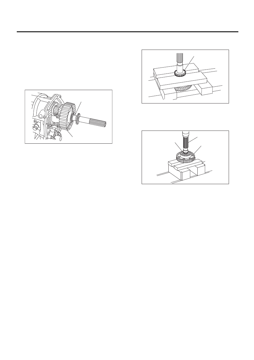
C: DISASSEMBLY
1) Using a press, remove revolution gear.
2) Using a press, remove the front and rear side
ball bearings and clutch hub.
(A) Rear driveshaft
(B) Center differential carrier
( A )
( B )
AT-00145
(A) Revolution gear
(A) Rear ball bearing
(B) Rear driveshaft
(C) Clutch hub
AT-00149
( A )
AT-00151
( A )
( B )
( C )
AT-100
AUTOMATIC TRANSMISSION
REAR DRIVE SHAFT
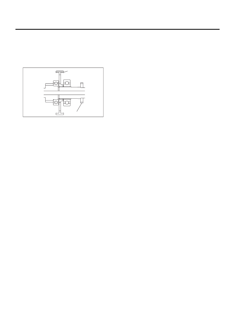
D: ASSEMBLY
Assemble in the reverse order of disassembly.
NOTE:
• Use a new revolution gear and ball bearings.
• Make sure the clutch hub is oriented in the cor-
rect direction.
E: INSPECTION
• Inspect parts to make sure there are no holes,
cuts, and that they are not dusty.
• Inspect extension end play and adjust it to within
the standard value. <Ref. to AT-95, VTD MODEL,
ADJUSTMENT, Transfer Clutch.>
(A) Front side
(B) Clutch hub
(C) Rear side
(D) Revolution gear
AT-00152
( A )
( B )
( C )
( D )
AT-101
AUTOMATIC TRANSMISSION
REDUCTION DRIVEN GEAR
29.Reduction Driven Gear
A: REMOVAL
1. MPT MODEL
1) Remove the transmission assembly from the ve-
hicle. <Ref. to AT-39, REMOVAL, Automatic
Transmission Assembly.>
2) Remove rear vehicle speed sensor, and sepa-
rate the transmission case and extension case.
<Ref. to AT-86, REMOVAL, Extension Case.>
3) Set the range select lever to “P”.
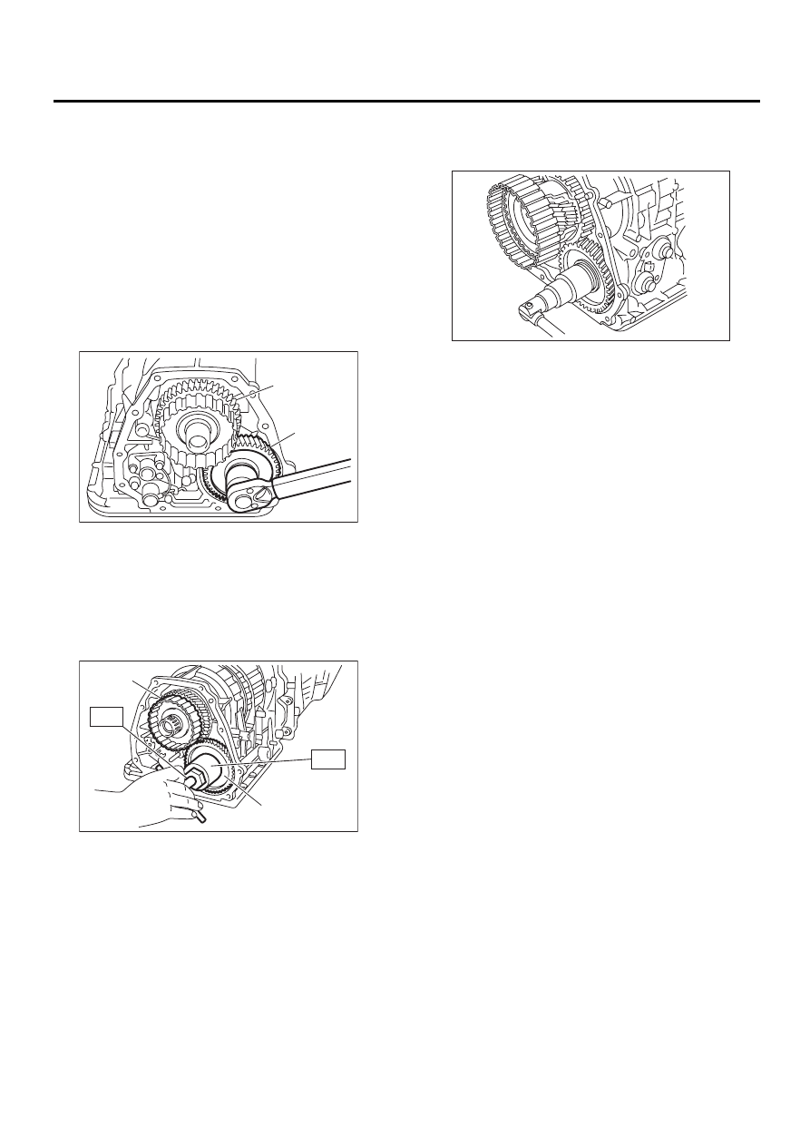
4) Straighten the staked portion, and remove the
lock nut.
5) Using the ST1 and ST2, extract the reduction
driven gear.
ST1
499737000
PULLER
ST2
899524100
PULLER SET
2. VTD MODEL
1) Remove the transmission assembly from the ve-
hicle. <Ref. to AT-39, REMOVAL, Automatic
Transmission Assembly.>
2) Remove rear vehicle speed sensor, and sepa-
rate the transmission case and extension case.
<Ref. to AT-86, REMOVAL, Extension Case.>
3) Remove the rear drive shaft. <Ref. to AT-99, RE-
MOVAL, Rear Drive Shaft.>
4) Set the range select lever to “P”.
5) Straighten the staked portion, and remove the
lock nut.
6) Using the ST1 and ST2, extract the reduction
driven gear.
ST1
499737000
PULLER
ST2
899524100
PULLER SET
7) Pull out the center differential assembly. <Ref. to
AT-106, REMOVAL, Center Differential Carrier.>
(A) Reduction driven gear
(B) Reduction drive gear
(A) Reduction driven gear
(B) Reduction drive gear
AT-00153
( A )
( B )
AT-00154
( A )
( B )
ST1
ST2
(A) Reduction driven gear
(B) Reduction drive gear
AT-00155
Нет комментариевНе стесняйтесь поделиться с нами вашим ценным мнением.
Текст