Subaru Legacy III (2000-2003 year). Service manual — part 549
AT-90
AUTOMATIC TRANSMISSION
TRANSFER CLUTCH
26.Transfer Clutch
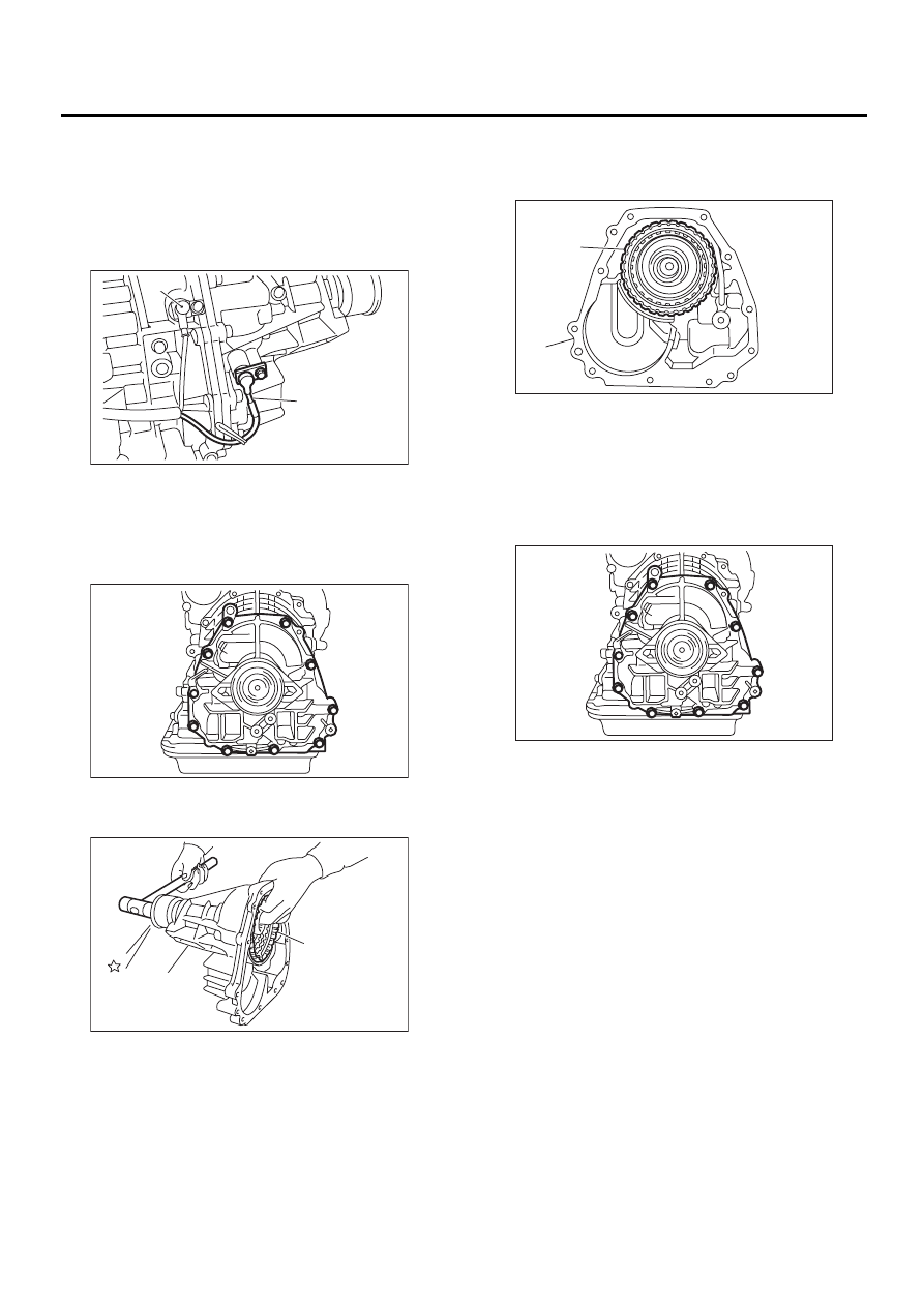
A: REMOVAL
1) Remove the transmission assembly from vehi-
cle. <Ref. to AT-39, REMOVAL, Automatic Trans-
mission Assembly.>
2) Remove rear vehicle speed sensor.
3) Separate transmission case and extension case
sections.
4) Take out the transfer clutch by lightly tapping the
end of the rear drive shaft.
B: INSTALLATION
1) Select the thrust needle bearing.
2) Install the transfer clutch assembly to the case.
3) Tighten bolts to secure the case.
Tightening torque:
25 N·m (2.5 kgf-m, 18.1 ft-lb)
4) Install the transmission assembly to vehicle.
<Ref. to AT-42, INSTALLATION, Automatic Trans-
mission Assembly.>
(A) Rear vehicle speed sensor
(B) Front vehicle speed sensor
(A) Transfer clutch
(B) Extension case
AT-00116
( A )
( B )
AT-00118
AT-00119
( A )
( B )
(A) Transfer clutch
(B) Extension case
AT-00125
( A )
( B )
AT-00118
AT-91
AUTOMATIC TRANSMISSION
TRANSFER CLUTCH
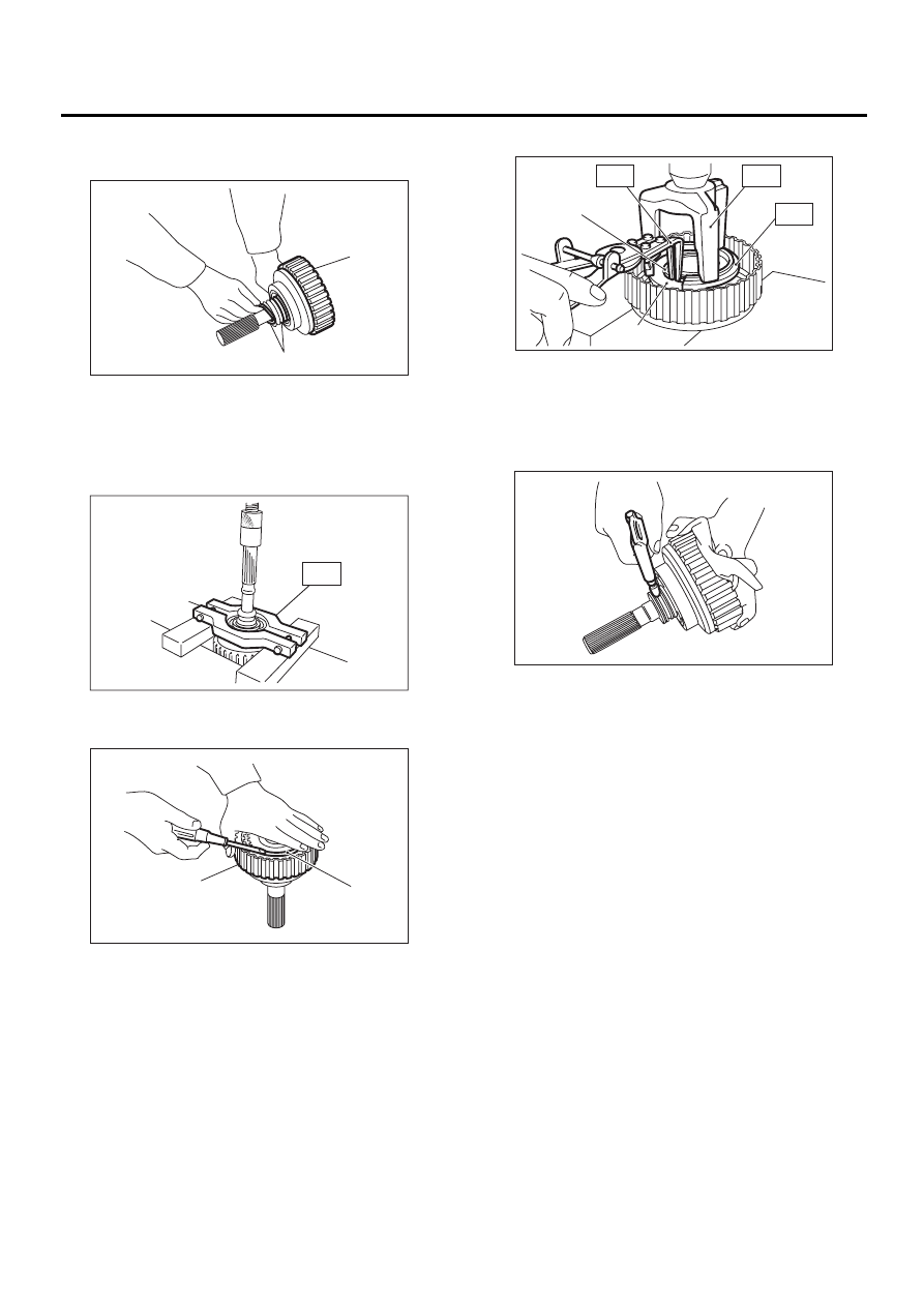
C: DISASSEMBLY
1) Remove the seal ring.
2) Using a press and ST, remove the ball bearing.
ST
498077600
REMOVER
3) Remove the snap ring, and take out the pressure
plate, drive plates, and driven plates.
4) Remove the snap ring with ST1, ST2 and ST3,
and take out the return spring and transfer clutch
piston seal.
ST1
399893600
PLIERS
ST2
398673600
COMPRESSOR
ST3
398623600
SEAT
5) Apply compressed air to the rear drive shaft to
remove the piston.
(A) Seal ring
(B) Transfer clutch
(A) Snap ring
(B) Transfer clutch
AT-00127
( A )
( B )
AT-00128
ST
AT-00129
( B )
( A )
(A) Snap ring
(B) Transfer piston seal
AT-00130
( A )
( B )
ST1
ST2
ST3
AT-00131
AT-92
AUTOMATIC TRANSMISSION
TRANSFER CLUTCH
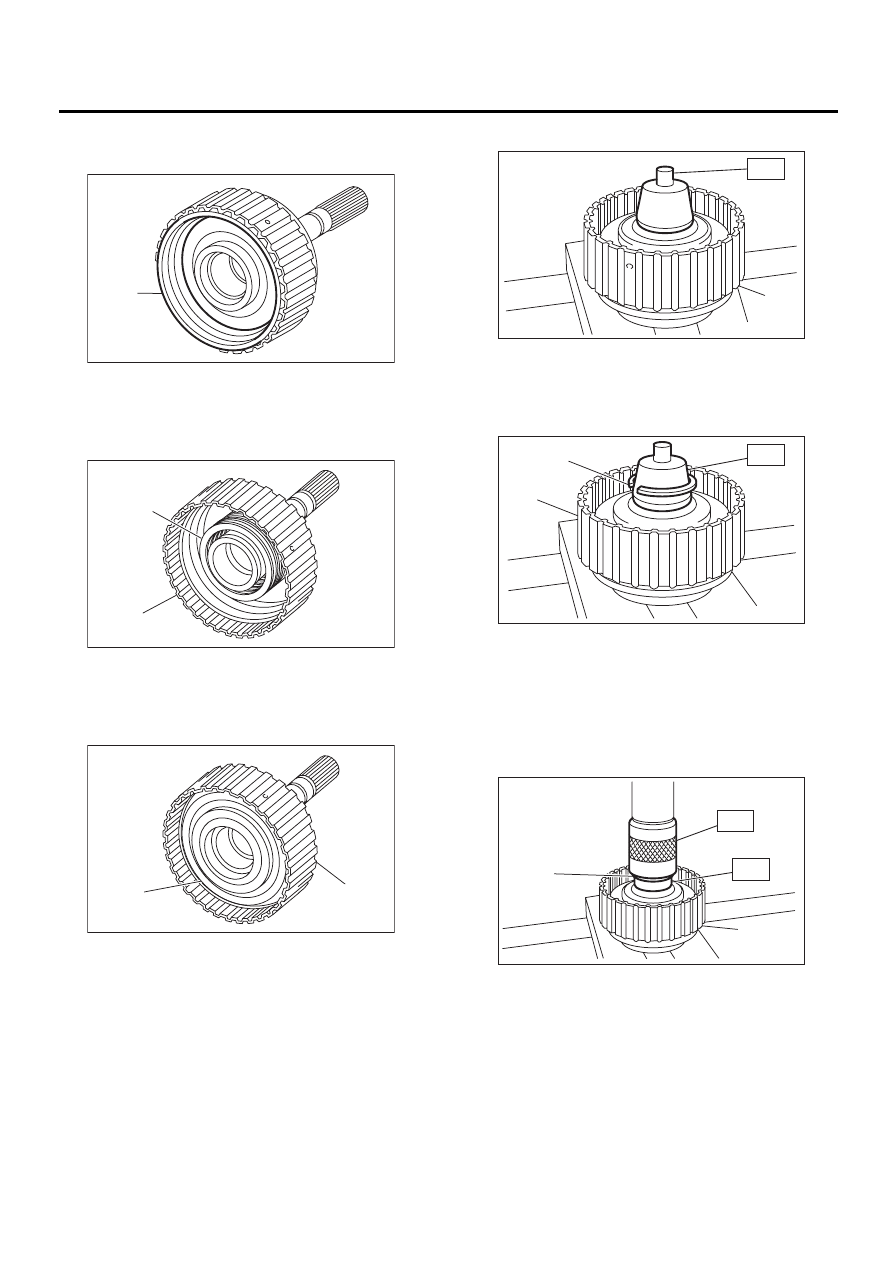
D: ASSEMBLY
1) Install the transfer clutch piston.
2) Install return spring to transfer piston.
3) Install transfer clutch piston seal.
4) Install ST to rear drive shaft.
ST
499257300
SNAP RING OUTER GUIDE
5) Install snap ring to ST.
ST
499257300
SNAP RING OUTER GUIDE
6) Using ST1 and ST2, install snap ring to rear
drive shaft.
ST1
499257300
SNAP RING OUTER GUIDE
ST2
499247400
INSTALLER
(A) Transfer clutch piston
(B) Rear drive shaft
(A) Return spring
(B) Rear drive shaft
(A) Transfer clutch piston seal
(B) Rear drive shaft
AT-00132
( A )
AT-00133
( A )
( B )
AT-00134
( B )
( A )
(A) Transfer clutch
(A) Snap ring
(B) Transfer clutch
(A) Snap ring
(B) Transfer clutch
AT-00135
( A )
ST
AT-00136
( B )
ST
( A )
AT-00137
( A )
( B )
ST1
ST2
AT-93
AUTOMATIC TRANSMISSION
TRANSFER CLUTCH
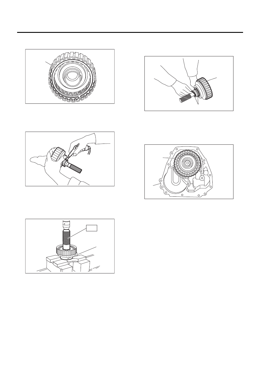
7) Install the driven plates, drive plates, pressure
plate and snap ring.
8) Apply compressed air to see if the assembled
parts move smoothly.
9) Check clearance between snap ring and pres-
sure plate. <Ref. to AT-94, INSPECTION, Transfer
Clutch.>
10) Press-fit a new ball bearing with ST.
ST
899580100
INSTALLER
11) Coat a new seal ring with vaseline, and install it
in the seal ring groove of the shaft.
NOTE:
Do not expand the seal ring excessively when in-
stalling.
12) Install the transfer clutch assembly without
damaging seal ring.
(A) Snap ring
(A) Ball bearing
AT-00138
( A )
AT-00139
AT-00140
( A )
ST
(A) Snap ring
(B) Transfer clutch
(A) Transfer clutch
(B) Extension case
AT-00141
( A )
( B )
AT-00125
( A )
( B )
Нет комментариевНе стесняйтесь поделиться с нами вашим ценным мнением.
Текст