Subaru Legacy III (2000-2003 year). Service manual — part 714
ABS-74
ABS (DIAGNOSTICS)
DIAGNOSTICS CHART WITH DIAGNOSIS CONNECTOR
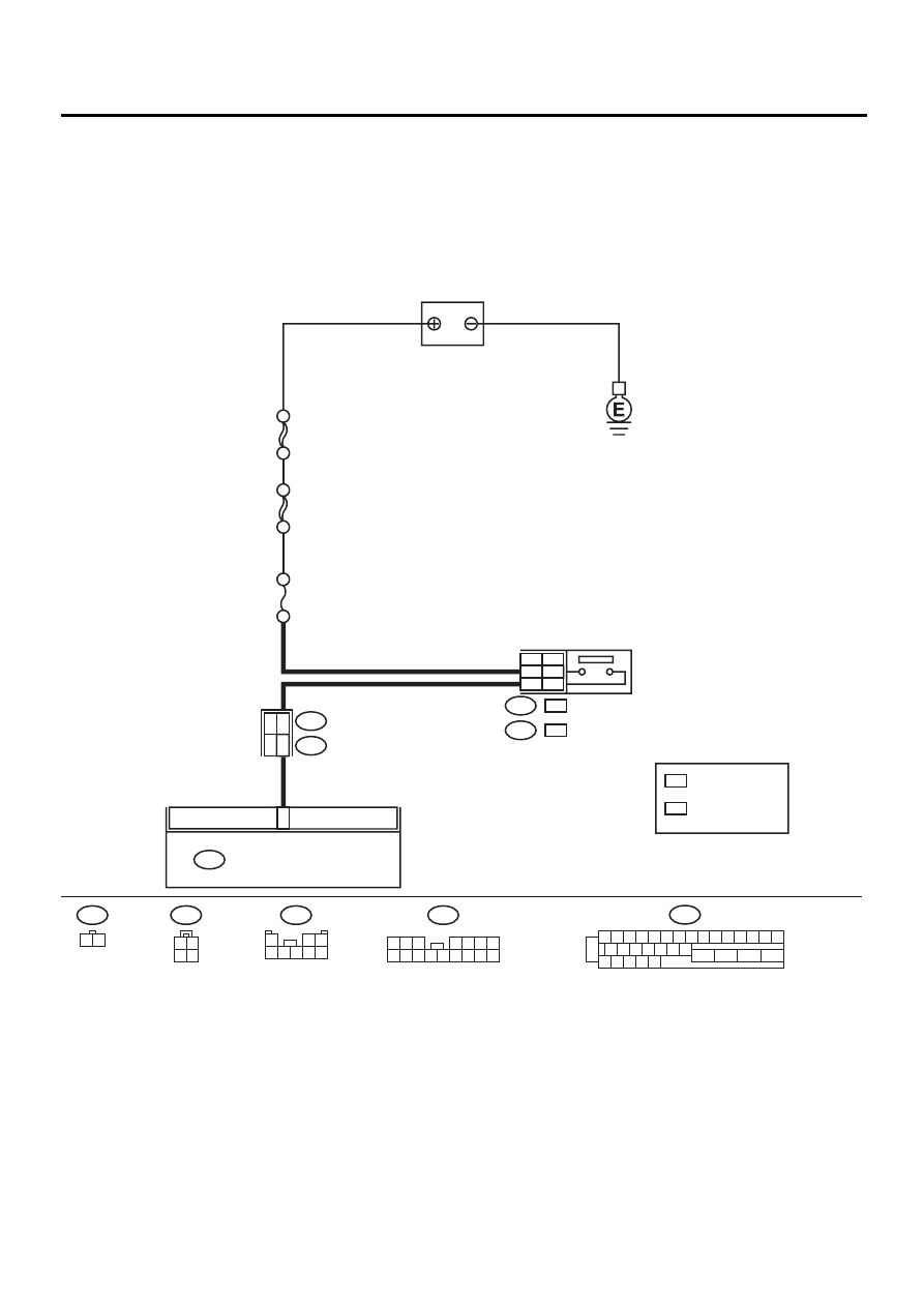
Z: DTC 54 ABNORMAL STOP LIGHT SWITCH
DIAGNOSIS:
• Faulty stop light switch
TROUBLE SYMPTOM:
• ABS does not operate.
WIRING DIAGRAM:
ABS00311
2
ABS CONTROL MODULE AND
HYDRAULIC CONTROL UNIT
F49
B64
1 2
1 2 3 4 5 6 7 8 9 10 11 12 13 14 15
16 17 18 19 20 21 22
27 28 29 30 31
23
24
25
26
F49
2
3
1
2
STOP LIGHT
SWITCH
B64
B65
:
:
: WITHOUT CRUISE
CONTROL
: WITH CRUISE
CONTROL
B65
1 2
3 4
B62
F45
NO
. 16 20A
BATTERY
SBF-1 100A
WC
OC
WC
OC
WC
OC
SBF-2 50A
6
7
RHD
LHD
:LHD
F45
1 2 3
4 5 6 7
8 9 10 11 12 13 14 15 16
F45
1
2 3
4 5 6 7 8

ABS-75
ABS (DIAGNOSTICS)
DIAGNOSTICS CHART WITH DIAGNOSIS CONNECTOR
Step
Value
Yes
No
1
CHECK STOP LIGHTS COME ON.
Depress the brake pedal.
Do stop lights come on?
Stop lights come on.
Repair stop lights
circuit.
2
CHECK OPEN CIRCUIT IN HARNESS.
1) Turn ignition switch to OFF.
2) Disconnect connector from ABSCM&H/U.
3) Depress brake pedal.
4) Measure voltage between ABSCM&H/U
connector and chassis ground.
Connector & terminal
(F49) No. 2 (+) — Chassis ground (
−−−−
):
Is the measured value within the specified
range?
10 - 15 V
Repair harness
between stop light
switch and
ABSCM&H/U.
3
CHECK POOR CONTACT IN CONNECTORS.
Is there poor contact in connector between
stop light switch and ABSCM&H/U?
There is no poor contact.
Repair connector.
4
CHECK ABSCM&H/U.
1) Connect all connectors.
2) Erase the memory.
3) Perform inspection mode.
4) Read out the DTC.
Is the same DTC still being output?
Same DTC is not indicated.
Replace
ABSCM&H/U.
<Ref. to ABS-6,
ABS Control Mod-
ule and Hydraulic
Control Unit
(ABSCM&H/U).>
5
CHECK ANY OTHER DTC APPEARANCE.
Are other DTC being output?
Other DTC is not indicated.
A temporary poor
contact.
Proceed with the
diagnosis corre-
sponding to the
DTC.
ABS-76
ABS (DIAGNOSTICS)
DIAGNOSTICS CHART WITH DIAGNOSIS CONNECTOR
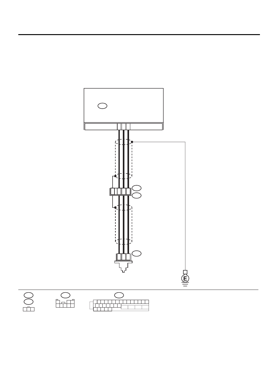
AA:DTC 56 ABNORMAL G SENSOR OUTPUT VOLTAGE
DIAGNOSIS:
• Faulty G sensor output voltage
TROUBLE SYMPTOM:
• ABS does not operate.
WIRING DIAGRAM:
ABS00312
F55
R70
F62
ABS CONTROL MODULE AND
HYDRAULIC CONTROL UNIT
ABS
G SENSOR
F49
2
1
3
F49
1 2 3 4 5 6 7 8 9 10 11 12 13 14 15
16 17 18 19 20 21 22
27 28 29 30 31
23
24
25
26
3
7
6
28
1
2
3
F55
R49
R70
2
8
30
1
2 3
4 5 6 7 8

ABS-77
ABS (DIAGNOSTICS)
DIAGNOSTICS CHART WITH DIAGNOSIS CONNECTOR
Step
Value
Yes
No
1
CHECK WHEELS FOR FREE TURNING.
Have the wheels been turned freely such as
when the vehicle is lifted up, or operated on a
rolling road?
Wheels have not turned freely. Go to step 2.
The ABS is nor-
mal. Erase the
DTC.
2
CHECK SPECIFICATIONS OF ABSCM&H/U.
Check specifications of the mark to the
ABSCM&H/U.
CG: AT (Except OUTBACK)
CH: MT (Except OUTBACK)
CI: AT (OUTBACK)
CJ: MT (OUTBACK)
Does the vehicle specification and the
ABSCM&H/U specification match?
Both are the same specifica-
tions.
Replace
ABSCM&H/U.
<Ref. to ABS-6,
ABS Control Mod-
ule and Hydraulic
Control Unit
(ABSCM&H/U).>
CAUTION:
Be sure to turn ig-
nition switch to
OFF when remov-
ing ABSCM&H/U.
3
CHECK INPUT VOLTAGE OF G SENSOR.
1) Turn ignition switch to OFF.
2) Remove console box.
3) Disconnect G sensor from body. (Do not
disconnect connector.)
4) Turn ignition switch to ON.
5) Measure voltage between G sensor con-
nector terminals.
Connector & terminal
(R70) No. 1 (+) — No. 3 (
−−−−
):
Is the measured value within the specified
range?
4.75 - 5.25 V
Repair harness/
connector
between G sensor
and ABSCM&H/U.
4
CHECK OPEN CIRCUIT IN G SENSOR OUT-
PUT HARNESS AND GROUND HARNESS.
1) Turn ignition switch to OFF.
2) Disconnect connector from ABSCM&H/U.
3) Measure resistance between ABSCM&H/U
connector terminals.
Connector & terminal
(F49) No. 6 — No. 28:
Is the measured value within the specified
range?
5.0 - 5.6 k
Ω
Repair harness/
connector
between G sensor
and ABSCM&H/U.
5
CHECK GROUND SHORT IN G SENSOR
OUTPUT HARNESS.
1) Disconnect connector from G sensor.
2) Measure resistance between ABSCM&H/U
connector and chassis ground.
Connector & terminal
(F49) No. 6 — Chassis ground:
Does the measured value exceed the spec-
ified value?
1 M
Ω
Repair harness
between G sensor
and ABSCM&H/U.
6
CHECK BATTERY SHORT OF HARNESS.
Measure voltage between ABSCM&H/U con-
nector and chassis ground.
Connector & terminal
(F49) No. 6 (+) — Chassis ground (
−−−−
):
Is the measured value less than the specified
value?
1 V
Repair harness
between G sensor
and ABSCM&H/U.
Нет комментариевНе стесняйтесь поделиться с нами вашим ценным мнением.
Текст