Subaru Legacy III (2000-2003 year). Service manual — part 715

ABS-78
ABS (DIAGNOSTICS)
DIAGNOSTICS CHART WITH DIAGNOSIS CONNECTOR
7
CHECK BATTERY SHORT OF HARNESS.
1) Turn ignition switch to ON.
2) Measure voltage between ABSCM&H/U
connector and chassis ground.
Connector & terminal
(F49) No. 6 (+) — Chassis ground (
−−−−
):
Is the measured value less than the speci-
fied value?
1 V
Repair harness
between G sensor
and ABSCM&H/U.
8
CHECK GROUND SHORT OF HARNESS.
Measure resistance between ABSCM&H/U
connector and chassis ground.
Connector & terminal
(F49) No. 28 — Chassis ground:
Does the measured value exceed the specified
value?
1 M
Ω
Repair harness
between G sensor
and ABSCM&H/U.
Replace
ABSCM&H/U.
<Ref. to ABS-6,
ABS Control Mod-
ule and Hydraulic
Control Unit
(ABSCM&H/U).>
9
CHECK G SENSOR.
1) Turn ignition switch to OFF.
2) Remove G sensor from vehicle.
3) Connect connector to G sensor.
4) Connect connector to ABSCM&H/U.
5) Turn ignition switch to ON.
6) Measure voltage between G sensor con-
nector terminals.
Connector & terminal
(R70) No. 2 (+) — No. 3 (
−−−−
):
Is the measured value within the specified
range when G sensor is horizontal?
2.1 - 2.5 V
Replace G sen-
sor. <Ref. to ABS-
21, G Sensor.>
10
CHECK G SENSOR.
Measure voltage between G sensor connector
terminals.
Connector & terminal
(R70) No. 2 (+) — No. 3 (
−−−−
):
Is the measured value within the specified
range when G sensor is inclined forward to
90
°
?
3.7 - 4.1 V
Replace G sen-
sor. <Ref. to ABS-
21, G Sensor.>
11
CHECK G SENSOR.
Measure voltage between G sensor connector
terminals.
Connector & terminal
(R70) No. 2 (+) — No. 3 (
−−−−
):
Is the measured value within the specified
range when G sensor is inclined backward to
90
°
?
0.5 - 0.9 V
Replace G sen-
sor. <Ref. to ABS-
21, G Sensor.>
12
CHECK POOR CONTACT IN CONNECTORS.
Is there poor contact in connector between
ABSCM&H/U and G sensor?
There is no poor contact.
Repair connector.
13
CHECK ABSCM&H/U.
1) Connect all connectors.
2) Erase the memory.
3) Perform inspection mode.
4) Read out the DTC.
Is the same DTC still being output?
Same DTC is not indicated.
Replace
ABSCM&H/U.
<Ref. to ABS-6,
ABS Control Mod-
ule and Hydraulic
Control Unit
(ABSCM&H/U).>
Step
Value
Yes
No

ABS-79
ABS (DIAGNOSTICS)
DIAGNOSTICS CHART WITH DIAGNOSIS CONNECTOR
14
CHECK ANY OTHER DTC APPEARANCE.
Are other DTC being output?
Other DTC is not indicated.
A temporary poor
contact.
Proceed with the
diagnosis corre-
sponding to the
DTC.
Step
Value
Yes
No
ABS-80
ABS (DIAGNOSTICS)
DIAGNOSTICS CHART WITH SUBARU SELECT MONITOR
13.Diagnostics Chart with Subaru Select Monitor
A: COMMUNICATION FOR INITIALIZING IMPOSSIBLE
DIAGNOSIS:
• Faulty harness connector
TROUBLE SYMPTOM:
• ABS warning light remains on.
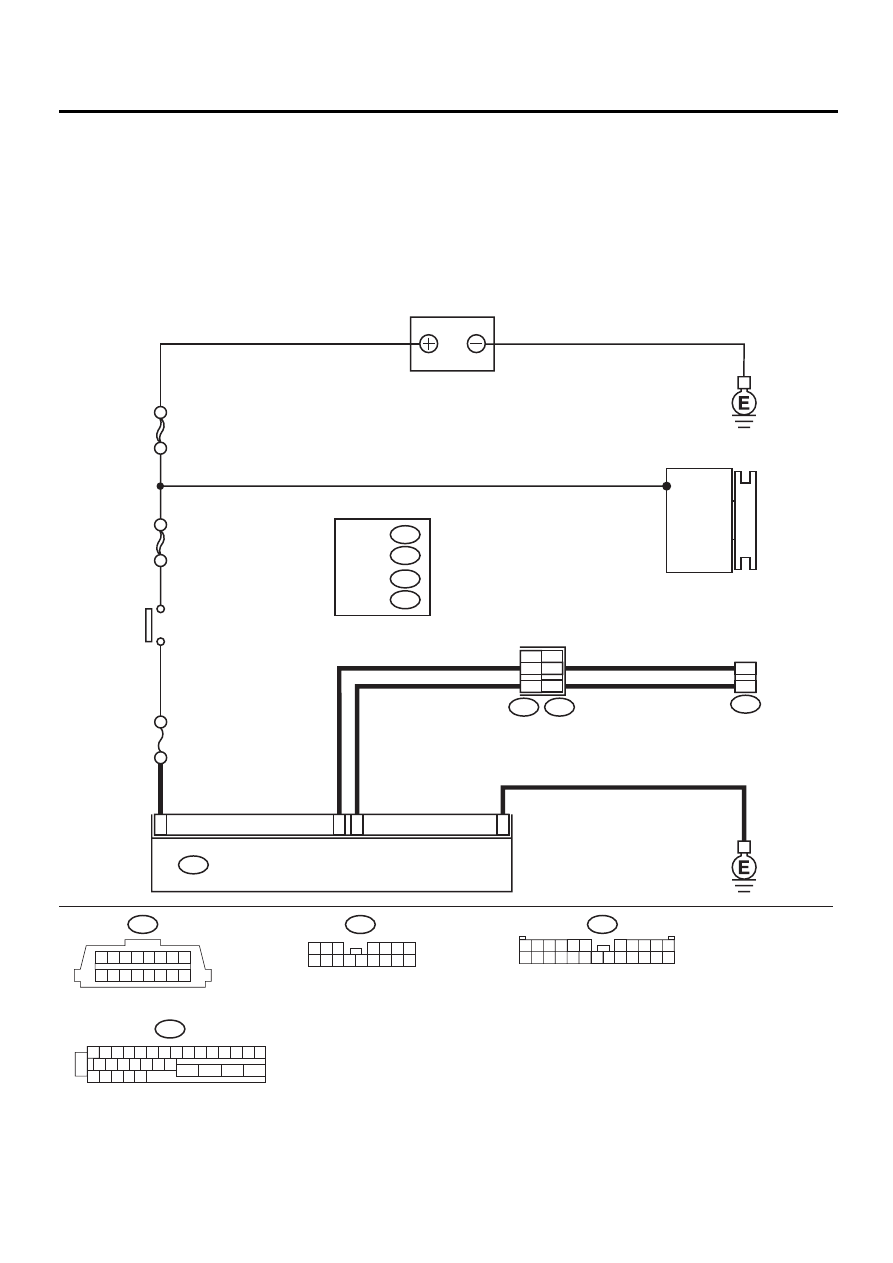
WIRING DIAGRAM:
ABS00313
BATTERY
1
23
20
5
ABS CONTROL MODULE AND HYDRAULIC CONTROL UNIT
F49
NO
. 18 15A
SBF-4 50A
SBF-1 100A
DATA LINK
CONNECTOR
5
4
B40
21
22
1 2 3 4 5 6 7 8 9 10 11 12 13 14 15
16 17 18 19 20 21 22
27 28 29 30 31
23
24
25
26
F2
1
2
B40
1 2 3 4 5 6 7 8
9 10 11 12 13 14 15 16
GENERATOR
IGNITION
SWITCH
F45
1 2
8 9
3
4 5 6 7
10 11 12 13 14 15 16
F49
3 4
1 2
8 9 10 11
12 13 14 15 16 17 18 19 20 21 22 23 24
5 6
7
RHD
LHD
1
*
1
*
2
*
F45
LHD
:
F2
RHD
2
*
B62
LHD
:
B100
RHD
:

ABS-81
ABS (DIAGNOSTICS)
DIAGNOSTICS CHART WITH SUBARU SELECT MONITOR
Step
Value
Yes
No
1
CHECK IGNITION SWITCH.
Is ignition switch to ON?
Ignition switch is to ON.
Turn ignition
switch to ON, and
select ABS mode
using the select
monitor.
2
CHECK BATTERY.
1) Turn ignition switch to OFF.
2) Measure battery voltage.
Does the measured value exceed the spec-
ified value?
11 V
Charge or replace
battery.
3
CHECK BATTERY TERMINAL.
Is there poor contact at battery terminal?
There is no poor contact.
Repair or tighten
battery terminal.
4
CHECK COMMUNICATION OF SELECT
MONITOR.
1) Turn ignition switch to ON.
2) Using the select monitor, check whether
communication to other systems can be
executed normally.
Are the name and year of the system dis-
played on the select monitor?
Name and year of the system
are displayed.
5
CHECK COMMUNICATION OF SELECT
MONITOR.
1) Turn ignition switch to OFF.
2) Disconnect ABSCM&H/U connector.
3) Check whether communication to other
systems can be executed normally.
Are the name and year of the system dis-
played on the select monitor?
Name and year of the system
are displayed.
6
CHECK HARNESS CONNECTOR BETWEEN
EACH CONTROL MODULE AND DATA LINK
CONNECTOR.
1) Turn ignition switch to OFF.
2) Disconnect ABSCM&H/U, cruise control
module and immobilizer control module
connectors.
3) Measure resistance between data link con-
nector and chassis ground.
Connector & terminal
(B40) No. 5 — Chassis ground:
(B40) No. 4 — Chassis ground:
Does the measured value exceed the spec-
ified value?
1 M
Ω
Repair harness
and connector
between each
control module
and data link con-
nector.
7
CHECK OUTPUT SIGNAL FOR ABSCM&H/
U.
1) Turn ignition switch to ON.
2) Measure voltage between data link connec-
tor and chassis ground.
Connector & terminal
(B40) No. 5 (+) — Chassis ground (
−−−−
):
(B40) No. 4 (+) — Chassis ground (
−−−−
):
Does the measured value exceed the spec-
ified value?
1 V
Repair harness
and connector
between each
control module
and data link con-
nector.
Нет комментариевНе стесняйтесь поделиться с нами вашим ценным мнением.
Текст