Subaru Legacy III (2000-2003 year). Service manual — part 713
ABS-70
ABS (DIAGNOSTICS)
DIAGNOSTICS CHART WITH DIAGNOSIS CONNECTOR
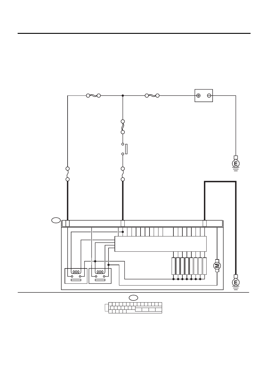
X: DTC 51 ABNORMAL VALVE RELAY
DIAGNOSIS:
• Faulty valve relay
TROUBLE SYMPTOM:
• ABS does not operate.
WIRING DIAGRAM:
ABS00297
ABS CONTROL MODULE AND
HYDRAULIC CONTROL UNIT
1 2 3 4 5 6 7 8 9 10 11 12 13 14 15
16 17 18 19 20 21 22
27 28 29 30 31
23
24
25
26
F49
24
1
23
VALVE RELAY
F49
MOTOR RELAY
FR OUTLET
FR INLET
RL OUTLET
RL INLET
RR OUTLET
RR INLET
FL OUTLET
FL INLET
SOLENOID
VA
L
V
E
PUMP MO
T
O
R
NO
. 8 30A
NO
. 18 15A
BATTERY
SBF-1 100A
SBF-3 50A
SBF-4 50A
IGNITION
SWITCH

ABS-71
ABS (DIAGNOSTICS)
DIAGNOSTICS CHART WITH DIAGNOSIS CONNECTOR
Step
Value
Yes
No
1
CHECK INPUT VOLTAGE OF ABSCM&H/U.
1) Turn ignition switch to OFF.
2) Disconnect connector from ABSCM&H/U.
3) Run the engine at idle.
4) Measure voltage between ABSCM&H/U
connector and chassis ground.
Connector & terminal
(F49) No. 1 (+) — Chassis ground (
−−−−
):
(F49) No. 24 (+) — Chassis ground (
−−−−
):
Is the measured value within the specified
range?
10 - 15 V
Repair harness
connector
between battery
and ABSCM&H/U.
2
CHECK GROUND CIRCUIT OF ABSCM&H/U.
1) Turn ignition switch to OFF.
2) Measure resistance between ABSCM&H/U
connector and chassis ground.
Connector & terminal
(F49) No. 23 — Chassis ground:
Is the measured value less than the speci-
fied value?
0.5
Ω
Repair
ABSCM&H/U
ground harness.
3
CHECK VALVE RELAY IN ABSCM&H/U.
Measure resistance between ABSCM&H/U
and terminals.
Terminals
No. 23 — No. 24 :
Does the measured value exceed the specified
value?
1 M
Ω
Replace
ABSCM&H/U.
<Ref. to ABS-6,
ABS Control Mod-
ule and Hydraulic
Control Unit
(ABSCM&H/U).>
4
CHECK POOR CONTACT IN CONNECTORS.
Is there poor contact in connectors between
generator, battery and ABSCM&H/U?
There is no poor contact.
Repair connector.
5
CHECK ABSCM&H/U.
1) Connect all connectors.
2) Erase the memory.
3) Perform inspection mode.
4) Read out the DTC.
Is the same DTC still being output?
Same DTC is not indicated.
Replace
ABSCM&H/U.
<Ref. to ABS-6,
ABS Control Mod-
ule and Hydraulic
Control Unit
(ABSCM&H/U).>
6
CHECK ANY OTHER DTC APPEARANCE.
Are other DTC being output?
Other DTC is not indicated.
A temporary poor
contact.
Proceed with the
diagnosis corre-
sponding to the
DTC.
ABS-72
ABS (DIAGNOSTICS)
DIAGNOSTICS CHART WITH DIAGNOSIS CONNECTOR
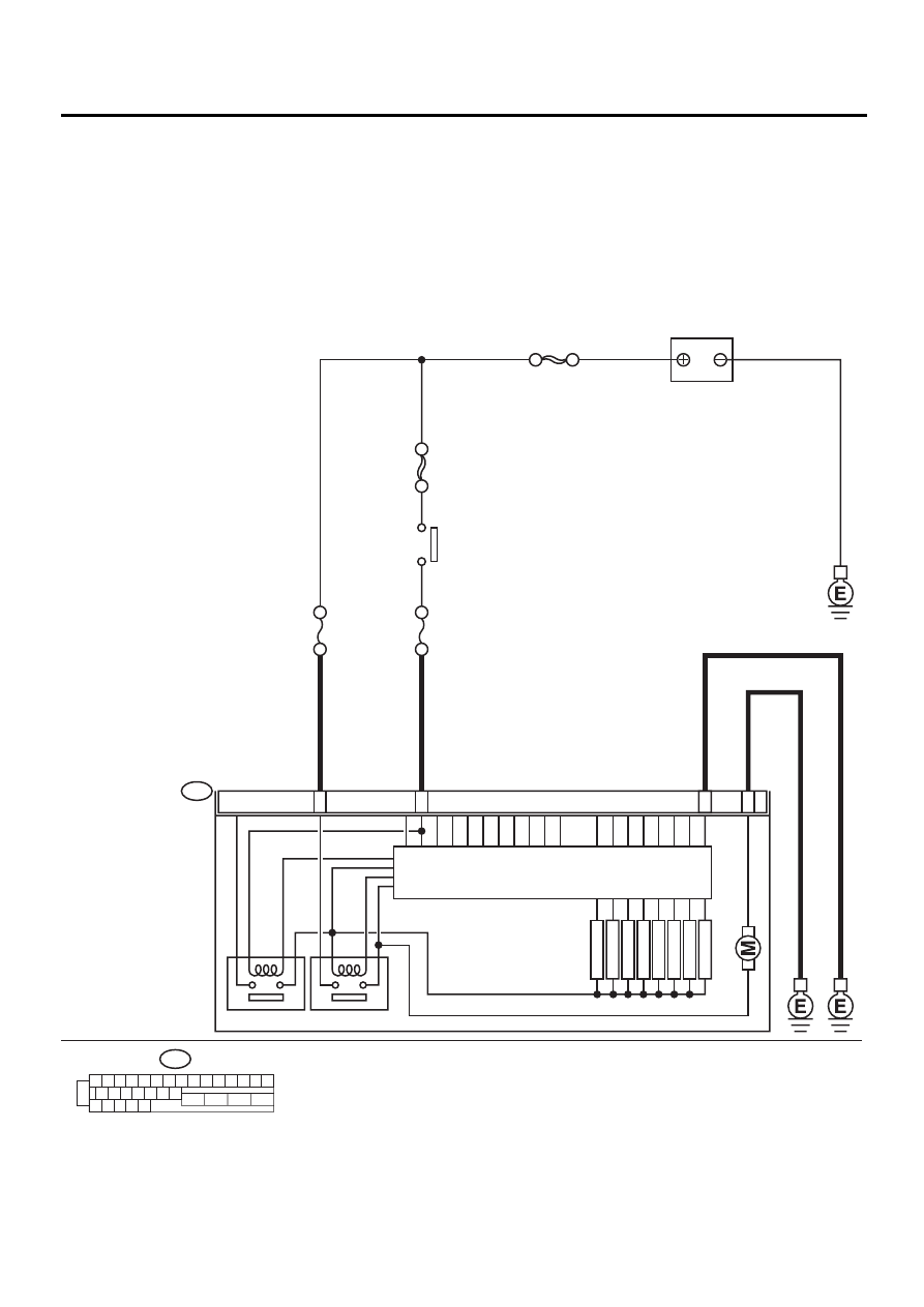
Y: DTC 52 ABNORMAL MOTOR AND/OR MOTOR RELAY
DIAGNOSIS:
• Faulty motor
• Faulty motor relay
• Faulty harness connector
TROUBLE SYMPTOM:
• ABS does not operate.
WIRING DIAGRAM:
ABS00298
ABS CONTROL MODULE AND
HYDRAULIC CONTROL UNIT
1 2 3 4 5 6 7 8 9 10 11 12 13 14 15
16 17 18 19 20 21 22
27 28 29 30 31
23
24
25
26
F49
25
1
23
26
VALVE RELAY
F49
MOTOR RELAY
FR OUTLET
FR INLET
RL OUTLET
RL INLET
RR OUTLET
RR INLET
FL OUTLET
FL INLET
SOLENOID
VA
L
V
E
PUMP MO
T
O
R
SBF HOLDER 50A
NO
. 10 15A
SBF-4 50A
IGNITION
SWITCH
SBF-1 100A
BATTERY

ABS-73
ABS (DIAGNOSTICS)
DIAGNOSTICS CHART WITH DIAGNOSIS CONNECTOR
Step
Value
Yes
No
1
CHECK INPUT VOLTAGE OF ABSCM&H/U.
1) Turn ignition switch to OFF.
2) Disconnect connector from ABSCM&H/U.
3) Turn ignition switch to ON.
4) Measure voltage between ABSCM&H/U
connector and chassis ground.
Connector & terminal
(F49) No. 25 (+) — Chassis ground (
−−−−
):
Is the measured value within the specified
range?
10 - 15 V
Repair harness/
connector
between battery
and ABSCM&H/U
and check fuse
SBF-holder.
2
CHECK GROUND CIRCUIT OF MOTOR.
1) Turn ignition switch to OFF.
2) Measure resistance between ABSCM&H/U
connector and chassis ground.
Connector & terminal
(F49) No. 26 — Chassis ground:
Is the measured value less than the speci-
fied value?
0.5
Ω
Repair
ABSCM&H/U
ground harness.
3
CHECK INPUT VOLTAGE OF ABSCM&H/U.
1) Run the engine at idle.
2) Measure voltage between ABSCM&H/U
connector and chassis ground.
Connector & terminal
(F49) No. 1 (+) — Chassis ground (
−−−−
):
Is the measured value within the specified
range?
10 - 15 V
Repair harness
connector
between battery,
ignition switch and
ABSCM&H/U.
4
CHECK GROUND CIRCUIT OF ABSCM&H/U.
1) Turn ignition switch to OFF.
2) Measure resistance between ABSCM&H/U
connector and chassis ground.
Connector & terminal
(F49) No. 23 — Chassis ground:
Is the measured value less than the speci-
fied value?
0.5
Ω
Repair
ABSCM&H/U
ground harness.
5
CHECK MOTOR OPERATION.
Operate the sequence control. <Ref. to ABS-
9, ABS Sequence Control.>
NOTE:
Use the diagnosis connector to operate the se-
quence control.
Can motor revolution noise (buzz) be heard
when carrying out the sequence control?
Operating sound is produced.
Replace
ABSCM&H/U.
<Ref. to ABS-6,
ABS Control Mod-
ule and Hydraulic
Control Unit
(ABSCM&H/U).>
6
CHECK POOR CONTACT IN CONNECTORS.
Turn ignition switch to OFF.
Is there poor contact in connector between
generator, battery and ABSCM&H/U?
There is no poor contact.
Repair connector.
7
CHECK ABSCM&H/U.
1) Connect all connectors.
2) Erase the memory.
3) Perform inspection mode.
4) Read out the DTC.
Is the same DTC still being output?
Same DTC is not indicated.
Replace
ABSCM&H/U.
<Ref. to ABS-6,
ABS Control Mod-
ule and Hydraulic
Control Unit
(ABSCM&H/U).>
8
CHECK ANY OTHER DTC APPEARANCE.
Are other DTC being output?
Other DTC is not indicated.
A temporary poor
contact.
Proceed with the
diagnosis corre-
sponding to the
DTC.
Нет комментариевНе стесняйтесь поделиться с нами вашим ценным мнением.
Текст