Subaru Legacy III (2000-2003 year). Service manual — part 712
ABS-66
ABS (DIAGNOSTICS)
DIAGNOSTICS CHART WITH DIAGNOSIS CONNECTOR
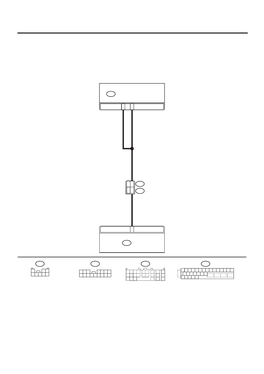
W: DTC 44 A COMBINATION OF AT CONTROL ABNORMAL
DIAGNOSIS:
• Combination of AT control faults
TROUBLE SYMPTOM:
• ABS does not operate.
WIRING DIAGRAM:
ABS00310
1 2 3 4 5 6 7 8 9 10 11 12 13 14 15
16 17 18 19 20 21 22
27 28 29 30 31
23
24
25
26
F49
31
3
ABS CONTROL MODULE AND
HYDRAULIC CONTROL UNIT
F49
TCM
B55
21
7
14
B62
F45
RHD
LHD
:LHD
F45
:RHD
1 2 3
4 5 6 7
8 9 10 11 12 13 14 15 16
F45
1
2 3
4 5 6 7 8
B55
1 2 3 4
10 11 12
19 20 21
13
5 6
14 15
7
8
9
16
17
18
22
23
24

ABS-67
ABS (DIAGNOSTICS)
DIAGNOSTICS CHART WITH DIAGNOSIS CONNECTOR
Step
Value
Yes
No
1
CHECK SPECIFICATIONS OF THE AB-
SCM&H/U.
Check specifications of the mark to the
ABSCM&H/U.
CG: AT (Except OUTBACK)
CH: MT (Except OUTBACK)
CI: AT (OUTBACK)
CJ: MT (OUTBACK)
Do the vehicle specification and the specifica-
tion of ABSCM&HU match?
Both are the same specifica-
tions.
Replace
ABSCM&H/U.
<Ref. to ABS-6,
ABS Control Mod-
ule and Hydraulic
Control Unit
(ABSCM&H/U).>
2
CHECK GROUND SHORT OF HARNESS.
1) Turn ignition switch to OFF.
2) Disconnect two connectors from TCM.
3) Disconnect connector from ABSCM&H/U.
4) Measure resistance between ABSCM&H/U
connector and chassis ground.
Connector & terminal
(F49) No. 3 — Chassis ground:
Does the measured value exceed the spec-
ified value?
1 M
Ω
Repair harness
between TCM and
ABSCM&H/U.
3
CHECK BATTERY SHORT OF HARNESS.
Measure voltage between ABSCM&H/U con-
nector and chassis ground.
Connector & terminal
(F49) No. 3 (+) — Chassis ground (
−−−−
):
Is the measured value less than the specified
value?
1 V
Repair harness
between TCM and
ABSCM&H/U.
4
CHECK BATTERY SHORT OF HARNESS.
1) Turn ignition switch to ON.
2) Measure voltage between ABSCM&H/U
connector and chassis ground.
Connector & terminal
(F49) No. 3 (+) — Chassis ground (
−−−−
):
Is the measured value less than the speci-
fied value?
1 V
Repair harness
between TCM and
ABSCM&H/U.
5
CHECK TCM.
1) Turn ignition switch to OFF.
2) Connect all connectors to TCM.
3) Turn ignition switch to ON.
4) Measure voltage between TCM connector
terminal and chassis ground.
Connector & terminal
(B55) No. 21 (+) — Chassis ground (
−−−−
):
Is the measured value within the specified
range?
10 - 15 V
6
CHECK AT.
Is the AT functioning normally?
Function of AT is normal.
Replace TCM.
Repair AT.
7
CHECK OPEN CIRCUIT OF HARNESS.
Measure voltage between ABSCM&H/U con-
nector and chassis ground.
Connector & terminal
(F49) No. 3 (+) — Chassis ground (
−−−−
):
(F49) No. 31 (+) — Chassis ground (
−−−−
):
Is the measured value within the specified
range?
10 - 15 V
Repair harness/
connector
between TCM and
ABSCM&H/U.
8
CHECK POOR CONTACT IN CONNECTORS.
Is there poor contact in connectors between
TCM and ABSCM&H/U?
There is no poor contact.
Repair connector.

ABS-68
ABS (DIAGNOSTICS)
DIAGNOSTICS CHART WITH DIAGNOSIS CONNECTOR
9
CHECK ABSCM&H/U.
1) Turn ignition switch to OFF.
2) Connect all connectors.
3) Erase the memory.
4) Perform inspection mode.
5) Read out the DTC.
Is the same DTC still being output?
Same DTC is not indicated.
Replace
ABSCM&H/U.
<Ref. to ABS-6,
ABS Control Mod-
ule and Hydraulic
Control Unit
(ABSCM&H/U).>
10
CHECK ANY OTHER DTC APPEARANCE.
Are other DTC being output?
Other DTC is not indicated.
A temporary poor
contact.
Proceed with the
diagnosis corre-
sponding to the
DTC.
Step
Value
Yes
No
ABS-69
ABS (DIAGNOSTICS)
DIAGNOSTICS CHART WITH DIAGNOSIS CONNECTOR
MEMO:
Нет комментариевНе стесняйтесь поделиться с нами вашим ценным мнением.
Текст