Subaru Legacy III (2000-2003 year). Service manual — part 212

EN(H4SOw/oOBD)-38
ENGINE (DIAGNOSTICS)
ENGINE MALFUNCTION INDICATOR LAMP (MIL)
Step
Value
Yes
No
1
CHECK HARNESS BETWEEN ECM CON-
NECTOR AND ENGINE GROUNDING TER-
MINAL.
1) Turn ignition switch to OFF.
2) Disconnect connector from ECM.
3) Measure resistance of harness between
ECM connector and engine ground.
Connector & terminal
(B135) No. 14 — Engine ground:
Is the measured value less than the speci-
fied value?
5
Ω
Repair short circuit
in harness
between ECM and
test mode connec-
tor.
Replace ECM.
<Ref. to
FU(H4SOw/
oOBD)-42, Engine
Control Module.>

EN(H4SOw/oOBD)-39
ENGINE (DIAGNOSTICS)
DIAGNOSTICS FOR ENGINE STARTING FAILURE
12.Diagnostics for Engine Starting Failure
A: PROCEDURE
1.
Inspection of starter motor circuit. <Ref. to EN(H4SOw/oOBD)-40, STARTER MOTOR CIRCUIT, Diagnostics for Engine
↓
2.
Inspection of ECM power supply and ground line. <Ref. to EN(H4SOw/oOBD)-43, CONTROL MODULE POWER SUPPLY
AND GROUND LINE, Diagnostics for Engine Starting Failure.>
↓
3.
Inspection of ignition control system. <Ref. to EN(H4SOw/oOBD)-46, IGNITION CONTROL SYSTEM, Diagnostics for Engine
↓
4.
Inspection of fuel pump circuit. <Ref. to EN(H4SOw/oOBD)-50, FUEL PUMP CIRCUIT, Diagnostics for Engine Starting Fail-
↓
5.
Inspection of fuel injector circuit. <Ref. to EN(H4SOw/oOBD)-53, FUEL INJECTOR CIRCUIT, Diagnostics for Engine Starting
EN(H4SOw/oOBD)-40
ENGINE (DIAGNOSTICS)
DIAGNOSTICS FOR ENGINE STARTING FAILURE
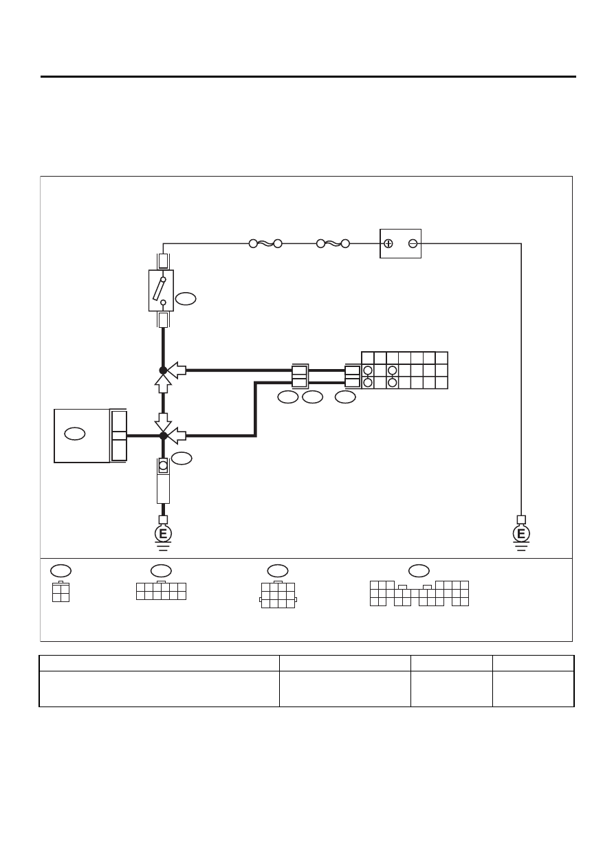
B: STARTER MOTOR CIRCUIT
CAUTION:
After repair or replacement of faulty parts, conduct CLEAR MEMORY and INSPECTION MODES. <Ref.
to EN(H4SOw/oOBD)-28, OPERATION, Clear Memory Mode.> and <Ref. to EN(H4SOw/oOBD)-26, OP-
ERATION, Inspection Mode.>
• WIRING DIAGRAM:
Step
Value
Yes
No
1
CHECK OPERATION OF STARTER MOTOR.
Does starter motor operate when the switch
starts?
Starter motor operates.
EN-01045
12
INHIBITOR SWITCH
STARTER
MOTOR
7
P
R
N
D
3
2
1
SBF-4
SBF-1
B14
12
11
T7
T3
B12
AT
MT
MT
5 6 7
8
2
1
9
4
3
10
24
22 23
25
11 12 13 14 15
26
27 28
16 17 18 19
20 21
B135
T7
1 2 3 4 5 6
7 8 9 10 11 12
28
B135
ECM
BATTERY
3
1
B72
IGNITION
SWITCH
AT
B72
3 4
1 2
B12
1 2 3 4
5 6 7 8
9 10 11 12

EN(H4SOw/oOBD)-41
ENGINE (DIAGNOSTICS)
DIAGNOSTICS FOR ENGINE STARTING FAILURE
2
CHECK DTC.
<Ref. to EN(H4SOw/oOBD)-24, OPERATION,
Read Diagnostic Trouble Code (DTC).>
Is the trouble code stored in memory? <Ref. to
EN(H4SOw/oOBD)-57, LIST, List of Diagnostic
Trouble Code (DTC).>
Trouble code is stored in mem-
ory.
Record DTC.
Repair the trouble
cause. <Ref. to
EN(H4SOw/
oOBD)-59, Diag-
nostic Procedure
with Diagnostic
Trouble Code
(DTC).>
3
CHECK INPUT SIGNAL FOR STARTER MO-
TOR.
1) Turn ignition switch to OFF.
2) Disconnect connector from starter motor.
3) Turn ignition switch to ST.
4) Measure power supply voltage between
starter motor connector terminal and
engine ground.
Connector & terminal
(B14) No. 1 (+) — Engine ground (
−−−−
):
NOTE:
On AT vehicles, place the selector lever in the
“P” or “N” position.
Does the measured value exceed the spec-
ified value?
10 V
4
CHECK GROUND CIRCUIT OF STARTER
MOTOR.
1) Turn ignition switch to OFF.
2) Disconnect terminal from starter motor.
3) Measure resistance of ground cable
between ground cable terminal and engine
ground.
Is the measured value less than the speci-
fied value?
5
Ω
Check starter
motor. <Ref. to
SC(H4SO)-6,
Starter.>
Repair open circuit
of ground cable.
5
CHECK HARNESS BETWEEN ECM AND
STARTER MOTOR CIRCUIT.
1) Turn ignition switch to OFF.
2) Measure resistance between starter motor
and ECM.
Connector & terminal
(B14) No. 1 — Engine ground:
Is the measured value less than the speci-
fied value?
1
Ω
Repair ground
short circuit.
6
CHECK HARNESS BETWEEN ECM AND
STARTER MOTOR CIRCUIT.
1) Turn ignition switch to START.
2) Measure resistance of fuse.
Connector & terminal
(B14) No. 1 — Engine ground:
Is the measured value less than the speci-
fied value?
1
Ω
Repair ground
short circuit.
Step
Value
Yes
No
Нет комментариевНе стесняйтесь поделиться с нами вашим ценным мнением.
Текст