Subaru Legacy III (2000-2003 year). Service manual — part 213

EN(H4SOw/oOBD)-42
ENGINE (DIAGNOSTICS)
DIAGNOSTICS FOR ENGINE STARTING FAILURE
7
CHECK HARNESS BETWEEN BATTERY
AND IGNITION SWITCH CONNECTOR.
1) Ignition switch to OFF.
2) Disconnect connector from ignition switch.
3) Measure power supply voltage between
ignition switch connector and chassis
ground.
Connector & terminal
(B72) No. 1 (+) — Chassis ground (
−−−−
):
Does the measured value exceed the spec-
ified value?
10 V
Repair open circuit
in harness
between ignition
switch and battery.
8
CHECK HARNESS BETWEEN BATTERY
AND IGNITION SWITCH CONNECTOR.
1) Connect connector to ignition switch.
2) Turn ignition switch to START.
3) Measure voltage between ignition switch
and chassis ground.
Connector & terminal
(B72) No. 3 (+) — Chassis ground (
−−−−
):
Does the measured value exceed the spec-
ified value?
10 V
Replace ignition
switch.
9
CHECK TRANSMISSION TYPE.
Is the vehicle AT?
Vehicle is AT.
Repair open circuit
between ignition
switch and starter
motor circuit.
10
CHECK INHIBITOR SWITCH CIRCUIT.
1) Turn ignition switch to OFF.
2) Place the selector lever in the “P” or “N”
position.
3) Separate transmission harness connector.
4) Measure resistance between transmission
harness connector receptacle's terminals.
Connector & terminal
(T3) No. 11 — No. 12:
Is the measured value less than the speci-
fied value?
1
Ω
Repair open circuit
in harness
between starter
motor and ignition
switch connector.
11
CHECK TRANSMISSION HARNESS.
1) Disconnect connector from inhibitor switch.
2) Measure resistance of harness between
transmission harness and inhibitor switch
connector.
Connector & terminal
(T3) No. 11 — (T7) No. 7:
(T3) No. 12 — (T7) No. 12:
Is the measured value less than the speci-
fied value?
1
Ω
Repair open circuit
in harness
between transmis-
sion harness and
inhibitor switch
connector.
12
CHECK POOR CONTACT.
Check poor contact in inhibitor switch connec-
tor.
Is there poor contact in inhibitor switch connec-
tor?
There is poor contact.
Repair poor con-
tact in inhibitor
switch connector.
Replace inhibitor
switch.
Step
Value
Yes
No
EN(H4SOw/oOBD)-43
ENGINE (DIAGNOSTICS)
DIAGNOSTICS FOR ENGINE STARTING FAILURE
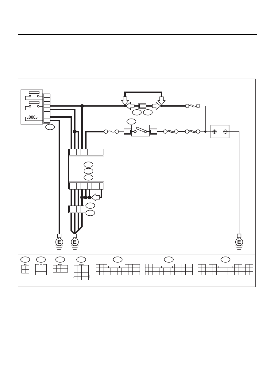
C: CONTROL MODULE POWER SUPPLY AND GROUND LINE
CAUTION:
After repair or replacement of faulty parts, conduct CLEAR MEMORY and INSPECTION MODES. <Ref.
to EN(H4SOw/oOBD)-28, OPERATION, Clear Memory Mode.> and <Ref. to EN(H4SOw/oOBD)-26, OP-
ERATION, Inspection Mode.>
• WIRING DIAGRAM:
EN-01046
C9
B7
C1
B19
C2
E3
B22
A8
A7
A27
C22
C21
B6
B25
13
15
14
16
B47
BATTERY
MAIN RELAY
1
2
3
5
4
6
F44
B61
SBF-5
6
LHD
RHD
RHD
SBF-4
SBF-1
4
1
B72
IGNITION
SWITCH
ECM
B134
A :
B135
B :
B136
C :
5 6 7
8
2
1
9
4
3
10
24
22 23
25
11 12 13 14 15
26
27 28
16 17 18 19
20 21
5
4
6 7
8
2
1
9
3
10
22
23
11 12 13 14 15
24 25
26 27
16 17 18
28 29
19 20
21
30
B135
B136
C:
B:
A: B134
1 2
3 4
5 6
7 8
9 10 11 12 13 14 15 16 17 18 19 20 21 22 23
24 25
26 27 28 29
30 31 32 33
34 35
B47
3
4
1
2
5
6
B72
3 4
1 2
B22
1 2 3 4
5 6 7 8
9 10 11 12
13 14 15 16
NO. 11
1 2 3 4
5 6 7 8
F44
LHD
MT

EN(H4SOw/oOBD)-44
ENGINE (DIAGNOSTICS)
DIAGNOSTICS FOR ENGINE STARTING FAILURE
Step
Value
Yes
No
1
CHECK MAIN RELAY.
1) Turn the ignition switch to OFF.
2) Remove main relay.
3) Connect battery to main relay terminals No.
1 and No. 2.
4) Measure resistance between main relay
terminals.
Terminals
No. 3 — No. 5:
No. 4 — No. 6:
Is the measured value less than the speci-
fied value?
10
Ω
Replace main
relay.
2
CHECK GROUND CIRCUIT OF ECM.
1) Disconnect connector from ECM.
2) Measure resistance of harness between
ECM and chassis ground.
Connector & terminal
(B136) No. 21 — Chassis ground:
(B136) No. 22 — Chassis ground:
(B135) No. 6 — Chassis ground (only
LHD model):
(B135) No. 25 — Chassis ground (only
MT model):
(B134) No. 27 — Chassis ground:
(B134) No. 8 — Chassis ground:
(B134) No. 7 — Chassis ground:
Is the measured value less than the speci-
fied value?
5
Ω
Repair open circuit
in harness
between ECM
connector and
engine grounding
terminal.
3
CHECK INPUT VOLTAGE OF ECM.
Measure voltage between ECM connector and
chassis ground.
Connector & terminal
(B136) No. 9 (+) — Chassis ground (–):
Does the measured value exceed the specified
value?
10 V
Repair open or
ground short cir-
cuit of power sup-
ply circuit.
4
CHECK INPUT VOLTAGE OF ECM.
1) Turn ignition switch to ON.
2) Measure voltage between ECM connector
and chassis ground.
Connector & terminal
(B135) No. 7 (+) — Chassis ground (–):
Does the measured value exceed the spec-
ified value?
10 V
Repair open or
ground short cir-
cuit of power sup-
ply circuit.
5
CHECK HARNESS BETWEEN ECM AND
MAIN RELAY CONNECTOR.
1) Turn ignition switch to OFF.
2) Measure resistance between ECM and
chassis ground.
Connector & terminal
(B135) No. 19 — Chassis ground:
Does the measured value exceed the spec-
ified value?
1 M
Ω
Repair ground
short circuit in har-
ness between
ECM connector
and main relay
connector, then
replace ECM.

EN(H4SOw/oOBD)-45
ENGINE (DIAGNOSTICS)
DIAGNOSTICS FOR ENGINE STARTING FAILURE
6
CHECK OUTPUT VOLTAGE FROM ECM.
1) Connect connector to ECM.
2) Turn ignition switch to ON.
3) Measure voltage between ECM connector
and chassis ground.
Connector & terminal
(B135) No. 19 (+) — Chassis ground (–):
Does the measured value exceed the spec-
ified value?
10 V
Replace ECM.
7
CHECK INPUT VOLTAGE OF MAIN RELAY.
Check voltage between main relay connector
and chassis ground.
Connector & terminal
(B47) No. 2 (+) — Chassis ground (–):
Does the measured value exceed the specified
value?
10 V
Repair open circuit
in harness
between ECM
connector and
main relay con-
nector.
8
CHECK GROUND CIRCUIT OF MAIN RE-
LAY.
1) Turn ignition switch to OFF.
2) Measure resistance between main relay
connector and chassis ground.
Connector & terminal
(B47) No. 1 — Chassis ground:
Is the measured value less than the speci-
fied value?
5
Ω
Repair open circuit
between main
relay and chassis
ground.
9
CHECK INPUT VOLTAGE OF MAIN RELAY.
Measure voltage between main relay connec-
tor and chassis ground.
Connector & terminal
(B47) No. 5 (+) — Chassis ground (
−−−−
):
(B47) No. 6 (+) — Chassis ground (
−−−−
):
Does the measured value exceed the specified
value?
10 V
Repair open or
ground short cir-
cuit in harness of
power supply cir-
cuit.
10
CHECK INPUT VOLTAGE OF ECM.
1) Connect main relay connector.
2) Turn ignition switch to ON.
3) Measure voltage between ECM connector
and chassis ground.
Connector & terminal
(B136) No. 1 (+) — Chassis ground (–):
(B136) No. 2 (+) — Chassis ground (–):
Does the measured value exceed the spec-
ified value?
10 V
Check ignition
control system.
<Ref. to
EN(H4SOw/
oOBD)-46, IGNI-
TION CONTROL
SYSTEM, Diag-
nostics for Engine
Starting Failure.>
Repair open or
ground short cir-
cuit in harness
between ECM
connector and
main relay con-
nector.
Step
Value
Yes
No
Нет комментариевНе стесняйтесь поделиться с нами вашим ценным мнением.
Текст