Subaru Legacy III (2000-2003 year). Service manual — part 211
EN(H4SOw/oOBD)-34
ENGINE (DIAGNOSTICS)
ENGINE MALFUNCTION INDICATOR LAMP (MIL)
D: CHECK ENGINE MALFUNCTION INDICATOR LAMP (MIL) DOES NOT GO
OFF.
• DIAGNOSIS:
• The CHECK ENGINE malfunction indicator lamp (MIL) circuit is shorted.
• TROUBLE SYMPTOM:
• Although MIL comes on when engine runs, trouble code is not shown on Subaru select monitor or OBD-
II general scan tool display.
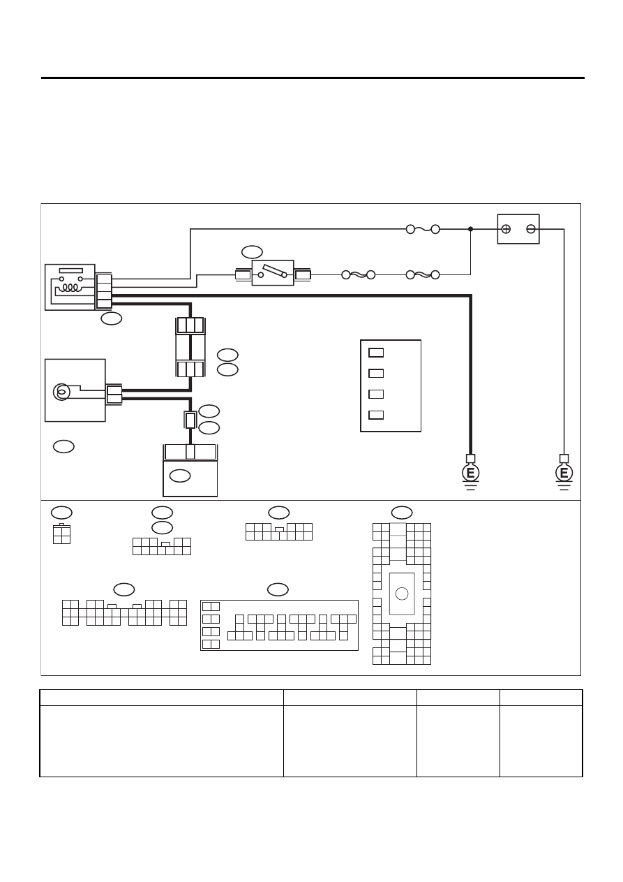
• WIRING DIAGRAM:
Step
Value
Yes
No
1
CHECK HARNESS BETWEEN COMBINA-
TION METER AND ECM CONNECTOR.
1) Turn ignition switch to OFF.
2) Disconnect connector from ECM.
3) Turn ignition switch to ON.
Does the MIL come on?
MIL illuminates.
Repair short circuit
in harness
between combina-
tion meter and
ECM connector.
Replace ECM.
<Ref. to
FU(H4SOw/
oOBD)-42, Engine
Control Module.>
EN-01043
IGNITION
RELAY
SBF-4
No. 5
SBF-1
A4
4
1
B157
B72
B134
B36
i1
IGNITION
SWITCH
B36
B4 B5 B6
A4 A5 A6
C5 C6
F6
D4 D5 D6
F1
H1
C4
G6
G1
C2
K1
M1 M2
K6
L1
D1 D2
A1 A2
B1 B2
I6
J6
L2
I1
J1
H6
M4 M5 M6
L4 L5 L6
N5 N6
O4 O5 O6
N4
P4 P5
N2
O1 O2
P1 P2
N3
O3
P3
P6
A3
B3
C3
E4 E5 E6
E1 E2
B134
1 2
3 4
5 6
7 8
9 10 11 12 13 14 15 16 17 18 19 20 21 22 23
24 25
26 27 28 29
30 31 32 33
34 35
i12
B152
1 2 3
4 5 6
7 8 9 10 11 12 13 14
B72
3 4
1 2
BATTERY
11
ECM
B157
10
11 12 13
14 15 16
17
18
19
20
21 22 23
24 25 26
27
28
29
30
31 32 33
34 35 36
37
38
1 2
9
3 4
5 6
7 8
COMBINATION
METER
5
3
i12
3
*
4
*
1
*
2
*
3
*
4
*
1
*
2
*
LHD : 10
RHD : 37
LHD : 11
RHD : 34
LHD : 13
RHD : 36
LHD : 9
RHD : 38
D3
B11
FUSE &
RELAY
BOX
i5
B :
B152
D :
i5
1 2 3
4 5
6 7 8 9 10 11 12
EN(H4SOw/oOBD)-35
ENGINE (DIAGNOSTICS)
ENGINE MALFUNCTION INDICATOR LAMP (MIL)
E: CHECK ENGINE MALFUNCTION INDICATOR LAMP (MIL) DOES NOT BLINK
AT A CYCLE OF 3 Hz.
• DIAGNOSIS:
• The CHECK ENGINE malfunction indicator lamp (MIL) circuit is open or shorted.
• Test mode connector circuit is in open.
• TROUBLE SYMPTOM:
• When inspection mode, MIL does not blink at a cycle of 3 Hz.
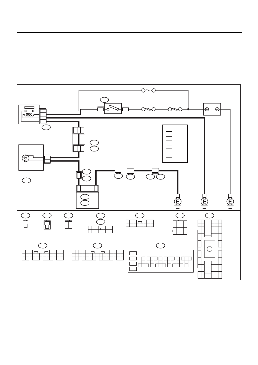
• WIRING DIAGRAM:
EN-01044
IGNITION
RELAY
SBF-4
No. 5
SBF-1
4
1
B157
B72
IGNITION
SWITCH
BATTERY
COMBINATION
METER
5
3
i12
B36
B4 B5 B6
A4 A5 A6
C5 C6
F6
D4 D5 D6
F1
H1
C4
G6
G1
C2
K1
M1 M2
K6
L1
D1 D2
A1 A2
B1 B2
I6
J6
L2
I1
J1
H6
M4 M5 M6
L4 L5 L6
N5 N6
O4 O5 O6
N4
P4 P5
N2
O1 O2
P1 P2
N3
O3
P3
P6
A3
B3
C3
E4 E5 E6
E1 E2
B134
1 2
3 4
5 6
7 8
9 10 11 12 13 14 15 16 17 18 19 20 21 22 23
24 25
26 27 28 29
30 31 32 33
34 35
B157
10
11 12 13
14 15 16
17
18
19
20
21 22 23
24 25 26
27
28
29
30
31 32 33
34 35 36
37
38
1 2
9
3 4
5 6
7 8
i12
1 2 3
4 5 6
7 8 9 10 11 12 13 14
B72
3 4
1 2
B75
B76
1
2
1
2
5 6 7
8
2
1
9
4
3
10
24
22 23
25
11 12 13 14 15
26
27 28
16 17 18 19
20 21
B135
1
1
B36
i1
B75
B76
A4
B22
E3
A11
B14
B: B135
A: B134
ECM
16
3
*
4
*
1
*
2
*
LHD : 10
RHD : 37
LHD : 11
RHD : 34
LHD : 13
RHD : 36
LHD : 9
RHD : 38
3
*
4
*
1
*
2
*
B22
1 2 3 4
5 6 7 8
9 10 11 12
13 14 15 16
B152
i5
1 2 3
4 5
6 7 8 9 10 11 12
D3
B11
FUSE &
RELAY
BOX
i5
B :
B152
D :

EN(H4SOw/oOBD)-36
ENGINE (DIAGNOSTICS)
ENGINE MALFUNCTION INDICATOR LAMP (MIL)
Step
Value
Yes
No
1
CHECK STATUS OF CHECK ENGINE MAL-
FUNCTION INDICATOR LAMP (MIL).
1) Turn ignition switch to OFF.
2) Disconnect test mode connector.
3) Turn ignition switch to ON.
Does the MIL come on?
MIL illuminates.
Repair the MIL cir-
cuit. <Ref. to
EN(H4SOw/
oOBD)-31,
CHECK ENGINE
MALFUNCTION
INDICATOR
LAMP (MIL)
DOES NOT
COME ON.,
Engine Malfunc-
tion Indicator
Lamp (MIL).>
2
CHECK OUTPUT SIGNAL FROM ECM.
Measure voltage between test mode connector
and chassis ground.
Connector & terminal
(B75) No. 1 (+) — Chassis ground (
−−−−
):
Is the measured value less than the specified
value?
1 V
3
CHECK HARNESS BETWEEN ECM AND
TEST MODE CONNECTOR.
1) Turn ignition switch to OFF.
2) Disconnect connector from ECM.
3) Measure resistance of harness between
ECM and test mode connector.
Connector & terminal
(B135) No. 14 — (B75) No. 1:
Is the measured value less than the speci-
fied value?
1
Ω
Repair harness
and connector.
NOTE:
In this case, repair
the following:
• Open circuit in
harness between
ECM and test
mode connector
4
CHECK POOR CONTACT.
Check poor contact in ECM connector.
Is there poor contact in ECM connector?
There is poor contact.
Repair poor con-
tact in ECM con-
nector.
Replace ECM.
<Ref. to
FU(H4SOw/
oOBD)-42, Engine
Control Module.>
5
CHECK HARNESS BETWEEN TEST MODE
CONNECTOR AND CHASSIS GROUND.
1) Turn ignition switch to OFF.
2) Disconnect connector from ECM.
3) Measure resistance of harness between
test mode connector and chassis ground.
Connector & terminal
(B76) No. 1 — Chassis ground:
Is the measured value less than the speci-
fied value?
1
Ω
Repair harness
and connector.
NOTE:
In this case, repair
the following:
• Open circuit in
harness between
test mode connec-
tor and chassis
ground
6
CHECK POOR CONTACT.
Check poor contact in ECM connector.
Is there poor contact in ECM connector?
There is poor contact.
Repair poor con-
tact in ECM con-
nector.
Replace ECM.
<Ref. to
FU(H4SOw/
oOBD)-42, Engine
Control Module.>
EN(H4SOw/oOBD)-37
ENGINE (DIAGNOSTICS)
ENGINE MALFUNCTION INDICATOR LAMP (MIL)
F: CHECK ENGINE MALFUNCTION INDICATOR LAMP (MIL) REMAINS BLINK-
ING AT A CYCLE OF 3 Hz.
• DIAGNOSIS:
• Test mode connector circuit is shorted.
• TROUBLE SYMPTOM:
• Even though test mode connector is disconnected, MIL blinks at a cycle of 3 Hz when ignition switch is
turned to ON.
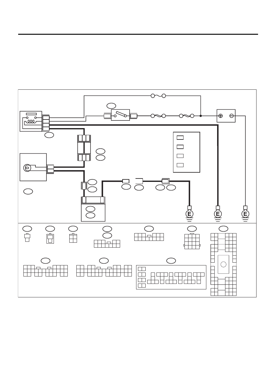
• WIRING DIAGRAM:
EN-01044
IGNITION
RELAY
SBF-4
No. 5
SBF-1
4
1
B157
B72
IGNITION
SWITCH
BATTERY
COMBINATION
METER
5
3
i12
B36
B4 B5 B6
A4 A5 A6
C5 C6
F6
D4 D5 D6
F1
H1
C4
G6
G1
C2
K1
M1 M2
K6
L1
D1 D2
A1 A2
B1 B2
I6
J6
L2
I1
J1
H6
M4 M5 M6
L4 L5 L6
N5 N6
O4 O5 O6
N4
P4 P5
N2
O1 O2
P1 P2
N3
O3
P3
P6
A3
B3
C3
E4 E5 E6
E1 E2
B134
1 2
3 4
5 6
7 8
9 10 11 12 13 14 15 16 17 18 19 20 21 22 23
24 25
26 27 28 29
30 31 32 33
34 35
B157
10
11 12 13
14 15 16
17
18
19
20
21 22 23
24 25 26
27
28
29
30
31 32 33
34 35 36
37
38
1 2
9
3 4
5 6
7 8
i12
1 2 3
4 5 6
7 8 9 10 11 12 13 14
B72
3 4
1 2
B75
B76
1
2
1
2
5 6 7
8
2
1
9
4
3
10
24
22 23
25
11 12 13 14 15
26
27 28
16 17 18 19
20 21
B135
1
1
B36
i1
B75
B76
A4
B22
E3
A11
B14
B: B135
A: B134
ECM
16
3
*
4
*
1
*
2
*
LHD : 10
RHD : 37
LHD : 11
RHD : 34
LHD : 13
RHD : 36
LHD : 9
RHD : 38
3
*
4
*
1
*
2
*
B22
1 2 3 4
5 6 7 8
9 10 11 12
13 14 15 16
B152
i5
1 2 3
4 5
6 7 8 9 10 11 12
D3
B11
FUSE &
RELAY
BOX
i5
B :
B152
D :
Нет комментариевНе стесняйтесь поделиться с нами вашим ценным мнением.
Текст