Subaru Legacy III (2000-2003 year). Service manual — part 210
EN(H4SOw/oOBD)-30
ENGINE (DIAGNOSTICS)
ENGINE MALFUNCTION INDICATOR LAMP (MIL)
11.Engine Malfunction Indicator Lamp (MIL)
A: PROCEDURE
B: ACTIVATION OF CHECK ENGINE
MALFUNCTION INDICATOR
LAMP (MIL)
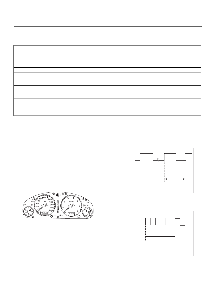
1) When ignition switch is turned to ON (engine
off), the CHECK ENGINE malfunction indicator
lamp (MIL) in the combination meter illuminates.
NOTE:
If the MIL does not illuminate, perform diagnostics
of the CHECK ENGINE light circuit or the combina-
tion meter circuit. <Ref. to IDI-14, Combination
Meter Assembly.>
2) After starting the engine, the MIL goes out. If it
does not, either the engine or the emission control
system is malfunctioning. <Ref. to EN(H4SOw/
oOBD)-2, PROCEDURE, Basic Diagnostic Proce-
dure.>
3) When ignition switch is turned to ON (engine off)
or to “START” with the test mode connector con-
nected, the MIL blinks at a cycle of 3 Hz.
1.
Activation of check engine malfunction indicator lamp (MIL). <Ref. to EN(H4SOw/oOBD)-30, ACTIVATION OF CHECK
ENGINE MALFUNCTION INDICATOR LAMP (MIL), Engine Malfunction Indicator Lamp (MIL).>
↓
2.
Check engine malfunction indicator lamp (MIL) does not come on. <Ref. to EN(H4SOw/oOBD)-31, CHECK ENGINE MAL-
FUNCTION INDICATOR LAMP (MIL) DOES NOT COME ON., Engine Malfunction Indicator Lamp (MIL).>
↓
3.
Check engine malfunction indicator lamp (MIL) does not go off. <Ref. to EN(H4SOw/oOBD)-34, CHECK ENGINE MAL-
FUNCTION INDICATOR LAMP (MIL) DOES NOT GO OFF., Engine Malfunction Indicator Lamp (MIL).>
↓
4.
Check engine malfunction indicator lamp (MIL) does not blink at a cycle of 3 Hz. <Ref. to EN(H4SOw/oOBD)-35, CHECK
↓
5.
Check engine malfunction indicator lamp (MIL) remains blinking at a cycle of 3 Hz. <Ref. to EN(H4SOw/oOBD)-37, CHECK
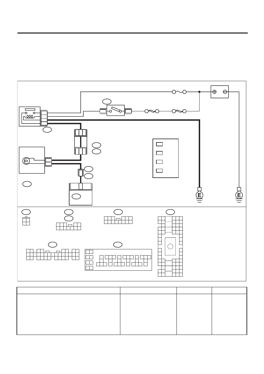
(A) Malfunction indicator lamp (MIL)
EN-01042
( A )
EN-00197
ON
MIL
OFF
ON
Ignition
switch
Engine
start
Misfire
start
1 sec.
EN-00198
ON
MIL
OFF
ON
Ignition
switch
1 sec.
EN(H4SOw/oOBD)-31
ENGINE (DIAGNOSTICS)
ENGINE MALFUNCTION INDICATOR LAMP (MIL)
C: CHECK ENGINE MALFUNCTION INDICATOR LAMP (MIL) DOES NOT COME
ON.
• DIAGNOSIS:
• The CHECK ENGINE malfunction indicator lamp (MIL) circuit is open or shorted.
• TROUBLE SYMPTOM:
• When ignition switch is turned ON (engine OFF), MIL does not come on.
• WIRING DIAGRAM:
Step
Value
Yes
No
1
CHECK OUTPUT SIGNAL FROM ECM.
1) Turn ignition switch to ON.
2) Measure voltage between ECM connector
and chassis ground.
Connector & terminal
(B134) No. 11 (+) — Chassis ground (
−−−−
):
Is the measured value less than the speci-
fied value?
1 V
EN-01043
IGNITION
RELAY
SBF-4
No. 5
SBF-1
A4
4
1
B157
B72
B134
B36
i1
IGNITION
SWITCH
B36
B4 B5 B6
A4 A5 A6
C5 C6
F6
D4 D5 D6
F1
H1
C4
G6
G1
C2
K1
M1 M2
K6
L1
D1 D2
A1 A2
B1 B2
I6
J6
L2
I1
J1
H6
M4 M5 M6
L4 L5 L6
N5 N6
O4 O5 O6
N4
P4 P5
N2
O1 O2
P1 P2
N3
O3
P3
P6
A3
B3
C3
E4 E5 E6
E1 E2
B134
1 2
3 4
5 6
7 8
9 10 11 12 13 14 15 16 17 18 19 20 21 22 23
24 25
26 27 28 29
30 31 32 33
34 35
i12
B152
1 2 3
4 5 6
7 8 9 10 11 12 13 14
B72
3 4
1 2
BATTERY
11
ECM
B157
10
11 12 13
14 15 16
17
18
19
20
21 22 23
24 25 26
27
28
29
30
31 32 33
34 35 36
37
38
1 2
9
3 4
5 6
7 8
COMBINATION
METER
5
3
i12
3
*
4
*
1
*
2
*
3
*
4
*
1
*
2
*
LHD : 10
RHD : 37
LHD : 11
RHD : 34
LHD : 13
RHD : 36
LHD : 9
RHD : 38
D3
B11
FUSE &
RELAY
BOX
i5
B :
B152
D :
i5
1 2 3
4 5
6 7 8 9 10 11 12
EN(H4SOw/oOBD)-32
ENGINE (DIAGNOSTICS)
ENGINE MALFUNCTION INDICATOR LAMP (MIL)
2
CHECK POOR CONTACT.
Does the MIL come on when shaking or pulling
ECM connector and harness?
MIL illuminates.
Repair poor con-
tact in ECM con-
nector.
3
CHECK ECM CONNECTOR.
Is ECM connector correctly connected?
ECM connector is connected
correctly.
Replace ECM.
Repair connection
of ECM connector.
4
CHECK HARNESS BETWEEN COMBINA-
TION METER AND ECM CONNECTOR.
1) Turn ignition switch to OFF.
2) Remove combination meter. <Ref. to IDI-
14, Combination Meter Assembly.>
3) Disconnect connector from ECM and com-
bination meter.
4) Measure resistance of harness between
ECM and combination meter connector.
Connector & terminal
(B134) No. 11 — (i12) No. 5:
Is the measured value less than the speci-
fied value?
1
Ω
Repair harness
and connector.
NOTE:
In this case, repair
the following:
• Open circuit in
harness between
ECM and combi-
nation meter con-
nector
• Poor contact in
coupling connector
5
CHECK POOR CONTACT.
Check poor contact in combination meter con-
nector. <Ref. to IDI-14, Combination Meter
Assembly.>
Is there poor contact in combination meter
connector?
There is poor contact.
Repair poor con-
tact in combination
meter connector.
6
CHECK HARNESS BETWEEN COMBINA-
TION METER AND IGNITION SWITCH CON-
NECTOR.
1) Turn ignition switch to ON.
2) Measure voltage between combination
meter connector and chassis ground.
Connector & terminal
(i12) No. 3 (+) — Chassis ground (
−−−−
):
Does the measured value exceed the spec-
ified value?
10 V
Check the follow-
ing and repair if
necessary.
NOTE:
• Broken down
ignition relay.
• Blown out fuse
(No. 5).
• If replaced fuse
(No. 5) blows eas-
ily, check the har-
ness for short
circuit of harness
between fuse (No.
5) and ignition
relay connector.
• Open or short
circuit in harness
between fuse (No.
5) and battery ter-
minal
• Open circuit in
harness between
fuse (No. 5) and
ignition relay con-
nector
• Poor contact in
ignition relay con-
nector
• Poor contact in
ignition switch
connector
Step
Value
Yes
No
EN(H4SOw/oOBD)-33
ENGINE (DIAGNOSTICS)
ENGINE MALFUNCTION INDICATOR LAMP (MIL)
7
CHECK POOR CONTACT.
Check poor contact in combination meter con-
nector. <Ref. to IDI-14, Combination Meter
Assembly.>
Is there poor contact in combination meter
connector?
There is poor contact.
Repair poor con-
tact in combination
meter connector.
Replace bulb or
combination
meter.
Step
Value
Yes
No
Нет комментариевНе стесняйтесь поделиться с нами вашим ценным мнением.
Текст