Subaru Legacy III (2000-2003 year). Service manual — part 983
EI-34
EXTERIOR/INTERIOR TRIM
CONSOLE BOX
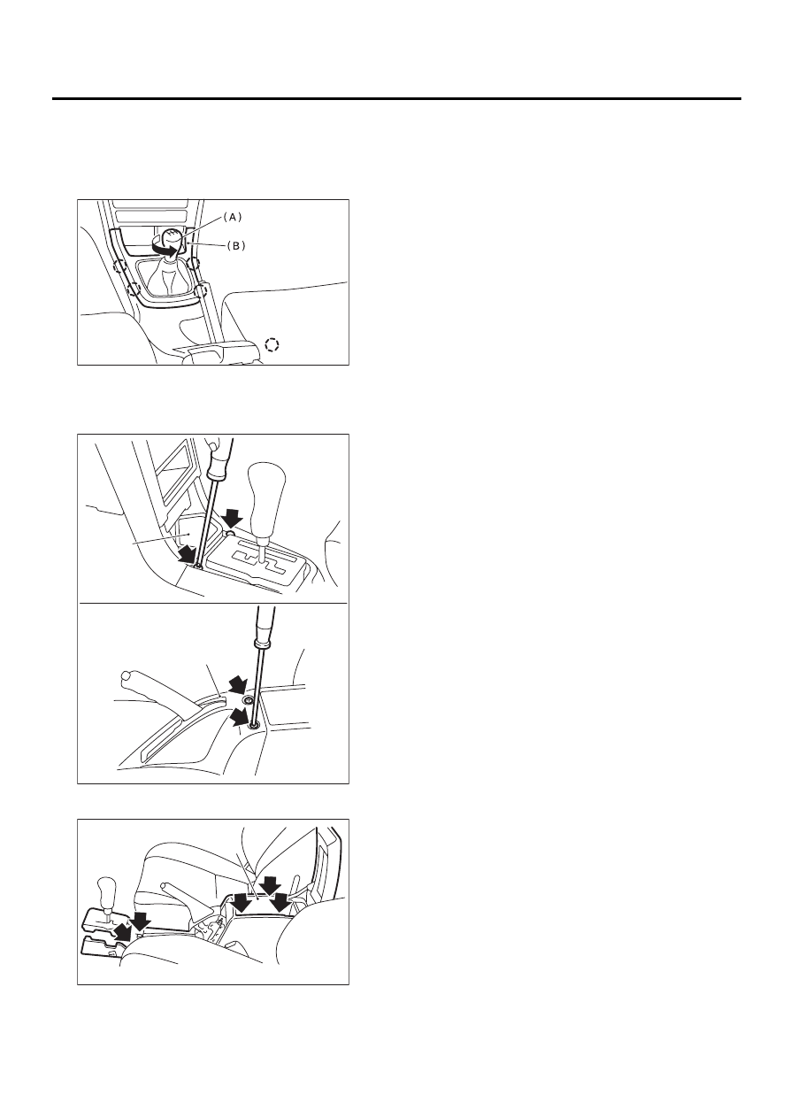
15.Console Box
A: REMOVAL
1) Remove shift knob (A) (MT model) and front cov-
er (B).
2) Remove tray (A) and console cover (B).
3) Remove console box (A).
B: INSTALLATION
Install in the reverse order of removal.
(1) Hook pawl
EI-00180
: ( 1 )
EI-00181
( A )
( B )
EI-00182
( A )
EI-35
EXTERIOR/INTERIOR TRIM
INSTRUMENT PANEL ASSEMBLY
16.Instrument Panel Assembly
A: REMOVAL
Airbag system wiring harness is routed near the
combination meter.
CAUTION:
• All airbag system wiring harness and con-
nectors are colored yellow. Do not use electri-
cal test equipment on these circuits.
• Be careful not to damage airbag system har-
ness when servicing the instrument panel.
NOTE:
The following location are for LHD model.
The locations for RHD model are symmetrically op-
posite.
1) Disconnect ground cable from battery.
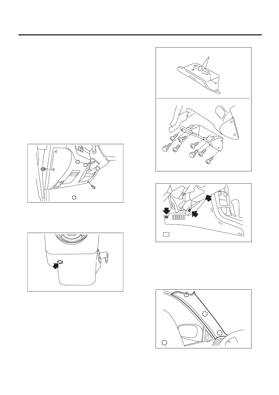
2) Remove lower cover.
3) Remove lower column cover and disconnect
harness connectors to steering column.
4) Remove steering column assembly (with steer-
ing wheel). <Ref. to PS-28, REMOVAL, Tilt Steer-
ing Column.>
5) Remove stopper (A) then remove glove box.
6) Remove side panel of both sides.
7) Remove passenger's airbag module. <Ref. to
AB-13, REMOVAL, Passenger's Airbag Module.>
8) Remove console box. <Ref. to EI-34, REMOV-
AL, Console Box.>
9) Remove front pillar upper trim of both sides.
(1) Hool pawl
EI-00183
: ( 1 )
EI-00184
(1) Hool pawl
(1) Hool pawl
EI-00185
( A )
EI-00186
: ( 1 )
EI-00187
: ( 1 )
EI-36
EXTERIOR/INTERIOR TRIM
INSTRUMENT PANEL ASSEMBLY
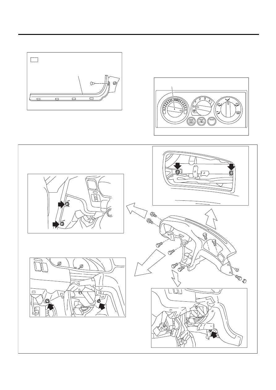
10) Remove front pillar lower trim of passenger
side.
11) Set temperature control switch (A) to “FULL
HOT” and then disconnect temperature control ca-
ble from bottom of heater unit. (Manual A/C
equipped model)
NOTE:
Do not move the switch and link when installing.
12) Remove instrument panel mounting bolts.
(1) Hool pawl
EI-00188
:
( A )
( 1 )
EI-00189
A/C
( A )
EI-00190
EI-37
EXTERIOR/INTERIOR TRIM
INSTRUMENT PANEL ASSEMBLY
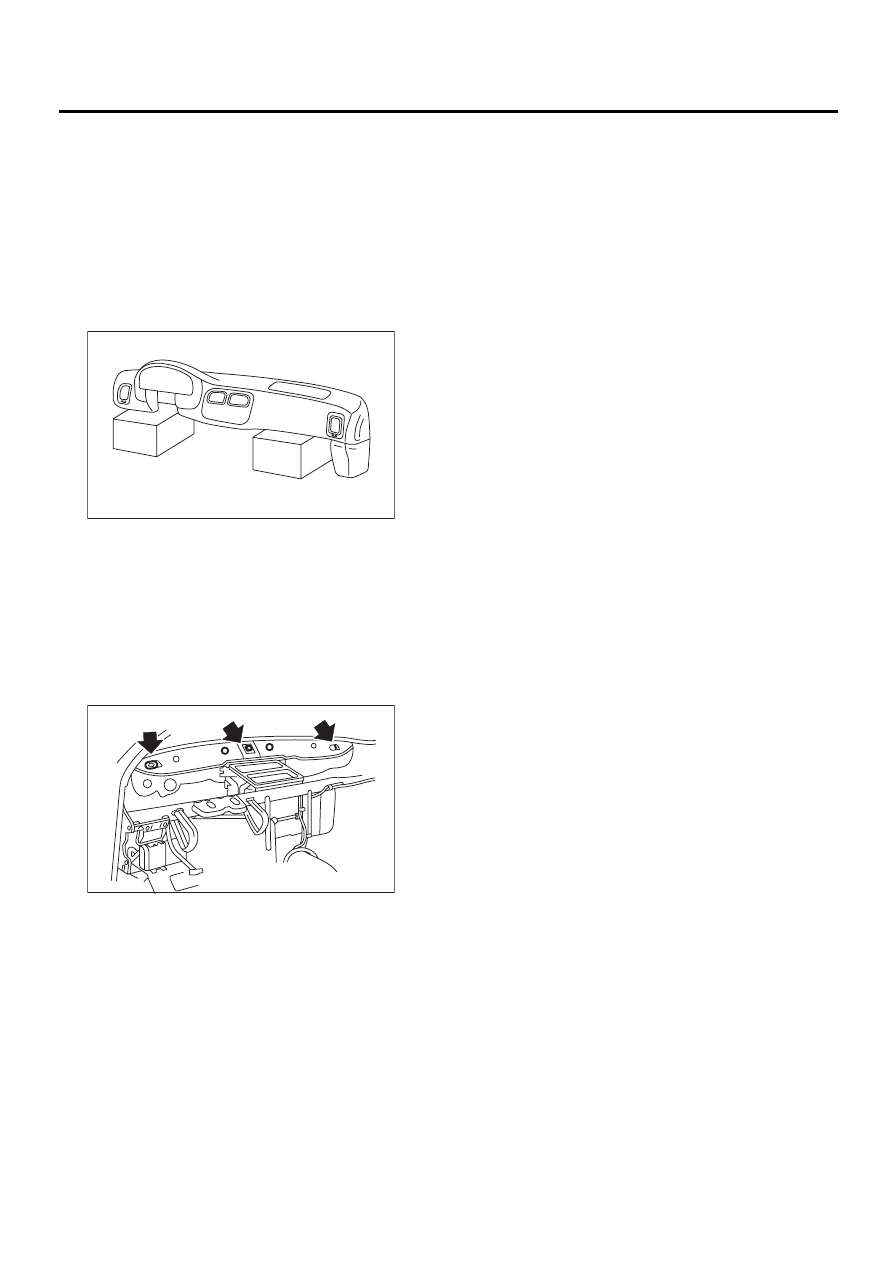
13) Disconnect harness connectors and remove in-
strument panel carefully.
CAUTION:
Do not pull the harness when disconnecting the
connector.
NOTE:
• If necessary, make matching marks for easy re-
assembly.
• When storing the removed instrument panel,
place it standing up on the floor.
B: INSTALLATION
Install in the reverse order of removal.
CAUTION:
Be careful not to snag the harness.
NOTE:
When setting the instrument panel into position,
push the three hooks into grommet (A) on the body
panel.
Tightening torque:
Refer to COMPONENT in General Descrip-
tion. <Ref. to EI-9, INSTRUMENT PANEL,
COMPONENT, General Description.>
EI-00192
EI-00193
( A )
( A )
( A )
Нет комментариевНе стесняйтесь поделиться с нами вашим ценным мнением.
Текст