Subaru Legacy III (2000-2003 year). Service manual — part 759

VDC-72
VDC (DIAGNOSTICS)
DIAGNOSTICS CHART WITH DIAGNOSIS CONNECTOR
4
CHECK BATTERY SHORT OF SOLENOID
VALVE.
1) Turn ignition switch to ON.
2) Measure voltage between VDCH/U con-
nector and chassis ground.
Connector & terminal
DTC 32/(VDC5) No. 1 (+) — Chassis
ground (
−−−−
):
DTC 34/(VDC5) No. 4 (+) — Chassis
ground (
−−−−
):
DTC 36/(VDC5) No. 3 (+) — Chassis
ground (
−−−−
):
DTC 38/(VDC5) No. 2 (+) — Chassis
ground (
−−−−
):
DTC 63/(VDC5) No. 10 (+) — Chassis
ground (
−−−−
):
DTC 64/(VDC5) No. 11 (+) — Chassis
ground (
−−−−
):
Is the measured value less than the speci-
fied value?
1 V
Replace VDCH/U.
<Ref. to VDC-8,
VDC Control Mod-
ule (VDCCM).>
5
CHECK BATTERY SHORT OF HARNESS.
1) Turn ignition switch to OFF.
2) Measure voltage between VDCCM connec-
tor and chassis ground.
Connector & terminal
DTC 32/(F87) No. 3 (+) — Chassis
ground (
−−−−
):
DTC 34/(F87) No. 51 (+) — Chassis
ground (
−−−−
):
DTC 36/(F87) No. 50 (+) — Chassis
ground (
−−−−
):
DTC 38/(F87) No. 4 (+) — Chassis
ground (
−−−−
):
DTC 63/(F87) No. 29 (+) — Chassis
ground (
−−−−
):
DTC 64/(F87) No. 2 (+) — Chassis
ground (
−−−−
):
Is the measured value less than the speci-
fied value?
1 V
Repair harness
between VDCCM
and VDCH/U.
6
CHECK BATTERY SHORT OF HARNESS.
1) Turn ignition switch to ON.
2) Measure voltage between VDCCM connec-
tor and chassis ground.
Connector & terminal
DTC 32/(F87) No. 3 (+) — Chassis
ground (
−−−−
):
DTC 34/(F87) No. 51 (+) — Chassis
ground (
−−−−
):
DTC 36/(F87) No. 50 (+) — Chassis
ground (
−−−−
):
DTC 38/(F87) No. 4 (+) — Chassis
ground (
−−−−
):
DTC 63/(F87) No. 29 (+) — Chassis
ground (
−−−−
):
DTC 64/(F87) No. 2 (+) — Chassis
ground (
−−−−
):
Is the measured value less than the speci-
fied value?
1 V
Repair harness
between VDCCM
and VDCH/U.
Step
Value
Yes
No

VDC-73
VDC (DIAGNOSTICS)
DIAGNOSTICS CHART WITH DIAGNOSIS CONNECTOR
7
CHECK GROUND SHORT OF HARNESS.
1) Turn ignition switch to OFF.
2) Measure resistance between VDCCM con-
nector and chassis ground.
Connector & terminal
DTC 32/(F87) No. 3 — Chassis ground:
DTC 34/(F87) No. 51 — Chassis ground:
DTC 36/(F87) No. 50 — Chassis ground:
DTC 38/(F87) No. 4 — Chassis ground:
DTC 63/(F87) No. 29 — Chassis ground:
DTC 64/(F87) No. 2 — Chassis ground:
Does the measured value exceed the spec-
ified value?
1 M
Ω
Repair harness
between VDCCM
and VDCH/U.
8
CHECK HARNESS/CONNECTOR BETWEEN
VDCCM AND VDCH/U.
1) Connect connector (F91) to VDCH/U.
2) Measure resistance between VDCCM con-
nector and VDCH/U connector.
Connector & terminal
DTC 32/(F87) No. 3 — (VDC2) No. 1:
DTC 34/(F87) No. 51 — (VDC2) No. 1:
DTC 36/(F87) No. 50 — (VDC2) No. 1:
DTC 38/(F87) No. 4 — (VDC2) No. 1:
DTC 63/(F87) No. 29 — (VDC2) No. 1:
DTC 64/(F87) No. 2 — (VDC2) No. 1:
Is the measured value within the specified
range?
3 — 6
Ω
Repair harness/
connector
between VDCCM
and VDCH/U.
9
CHECK POOR CONTACT IN CONNECTORS.
Is there poor contact in connectors between
VDCCM and VDCH/U?
There is poor contact.
Repair connector.
10
CHECK VDCCM.
1) Connect all connectors.
2) Erase the memory.
3) Perform inspection mode.
4) Read out the diagnostic trouble code.
Is the same diagnostic trouble code as in
the current diagnosis still being output?
Same DTC indicated.
Replace VDCCM.
<Ref. to VDC-8,
VDC Control Mod-
ule (VDCCM).>
11
CHECK ANY OTHER DIAGNOSTIC TROU-
BLE CODES APPEARANCE.
Are other diagnostic trouble codes being out-
put?
Other DTC indicated.
Proceed with the
diagnosis corre-
sponding to the
diagnostic trouble
code.
A temporary poor
contact.
Step
Value
Yes
No
VDC-74
VDC (DIAGNOSTICS)
DIAGNOSTICS CHART WITH DIAGNOSIS CONNECTOR
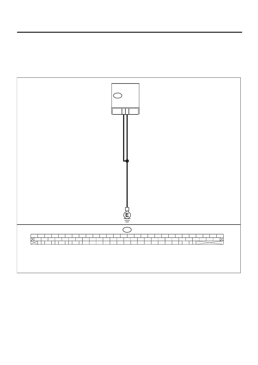
AA:DTC 41 ABNORMAL VDC CONTROL MODULE
DIAGNOSIS:
• Faulty VDCCM
TROUBLE SYMPTOM:
• ABS does not operate.
• VDC does not operate.
WIRING DIAGRAM:
VDC00143
VDC
CONTROL
MODULE
1
55
F87
56 57
59 60
62 63
65
82 83
80
27
28
25
26
23
24
21
22
19
20
17
18
15
16
13
14
11
12
9
10
7
8
5
6
3
4
1
2
54
55
52
53
50
51
81
48
49
46
47
44
45
78
79
76
77
75
42
43
40
41
74
72
73
70
71
39
37
38
35
36
69
67
68
66
33
34
61
64
31
32
29
30
58
F87
VDC-75
VDC (DIAGNOSTICS)
DIAGNOSTICS CHART WITH DIAGNOSIS CONNECTOR
Step
Value
Yes
No
1
CHECK GROUND CIRCUIT OF VDCCM.
1) Turn ignition switch to OFF.
2) Disconnect connector from VDCCM.
3) Measure resistance between VDCCM and
chassis ground.
Connector & terminal
(F87) No. 1 — Chassis ground:
(F87) No. 55 — Chassis ground:
Is the measured value less than the speci-
fied value?
0.5
Ω
Repair VDCCM
ground harness.
2
CHECK POOR CONTACT IN CONNECTORS.
Is there poor contact in connectors between
battery, ignition switch and VDCCM?
There is poor contact.
Repair connector.
3
CHECK SOURCES OF SIGNAL NOISE.
Is the car telephone or the wireless transmitter
properly installed?
Tightened securely.
Properly install the
car telephone or
the wireless trans-
mitter.
4
CHECK SOURCES OF SIGNAL NOISE.
Are noise sources (such as an antenna)
installed near the sensor harness?
Installed properly.
Install the noise
sources apart from
the sensor har-
ness.
5
CHECK VDCCM.
1) Connect all connectors.
2) Erase the memory.
3) Perform inspection mode.
4) Read out the diagnostic trouble code.
Is the same diagnostic trouble code as in
the current diagnosis still being output?
Same DTC indicated.
Replace VDCCM.
<Ref. to VDC-8,
VDC Control Mod-
ule (VDCCM).>
6
CHECK ANY OTHER DIAGNOSTIC TROU-
BLE CODES APPEARANCE.
Are other diagnostic trouble codes being out-
put?
Other DTC indicated.
Proceed with the
diagnosis corre-
sponding to the
diagnostic trouble
code.
A temporary poor
contact.
Нет комментариевНе стесняйтесь поделиться с нами вашим ценным мнением.
Текст