Infiniti G20 (P11). Manual — part 295
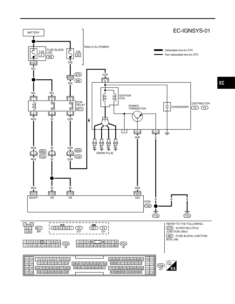
Wiring Diagram
NCEC0324
TEC833
GI
MA
EM
LC
FE
CL
MT
AT
AX
SU
BR
ST
RS
BT
HA
SC
EL
IDX
IGNITION SIGNAL
Wiring Diagram
EC-591
Diagnostic Procedure
NCEC0325
1
INSPECTION START
Turn ignition switch “OFF”, and restart engine.
Is engine running?
Yes or No
Yes (With CONSULT-II)
©
GO TO 2.
Yes (Without CONSULT-
II)
©
GO TO 3.
No
©
GO TO 4.
2
CHECK OVERALL FUNCTION
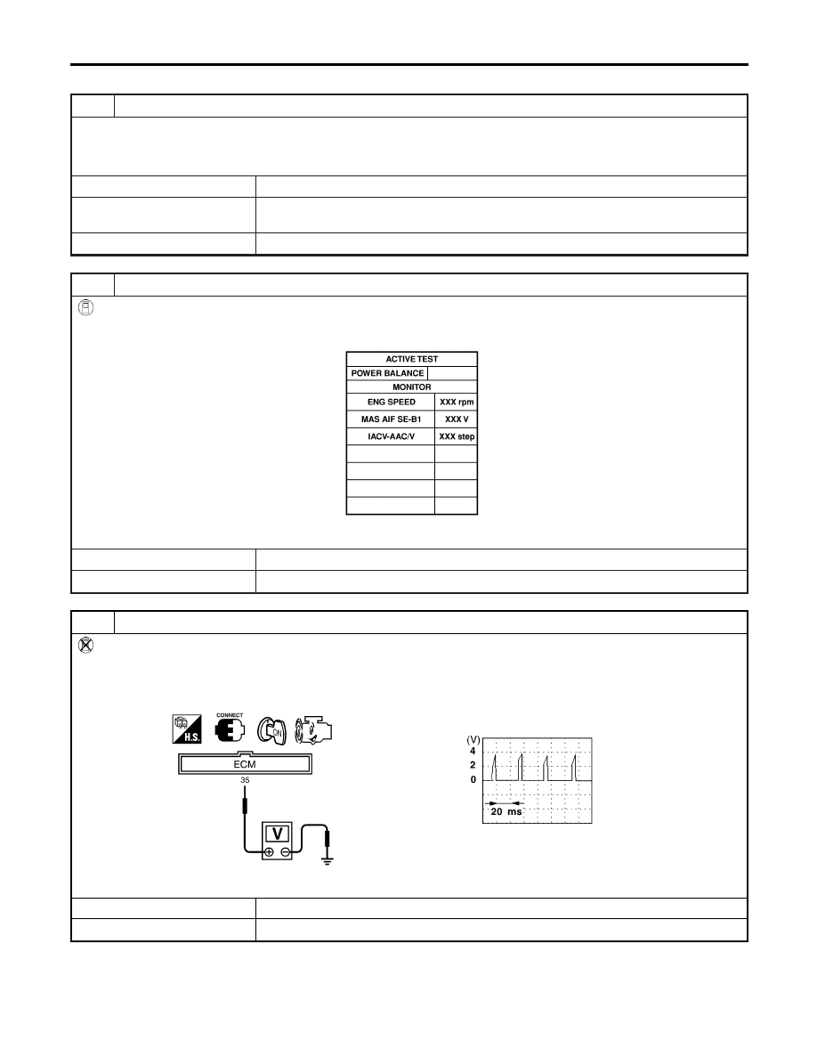
With CONSULT-II
1. Perform “POWER BALANCE” in “ACTIVE TEST” mode with CONSULT-II.
2. Make sure that all circuits do not produce a momentary engine speed drop.
SEF070Y
OK or NG
OK
©
INSPECTION END
NG
©
GO TO 4.
3
CHECK OVERALL FUNCTION
Without CONSULT-II
1. Let engine idle.
2. Read the voltage signal between ECM terminal 35 and ground with an oscilloscope.
3. Verify that the oscilloscope screen shows the signal wave as shown below.
SEC578C
OK or NG
OK
©
INSPECTION END
NG
©
GO TO 4.
IGNITION SIGNAL
Diagnostic Procedure
EC-592
4
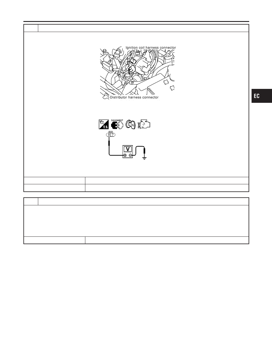
CHECK POWER SUPPLY
1. Turn ignition switch “OFF”.
2. Disconnect ignition coil harness connector.
SEF848X
3. Turn ignition switch “ON”.
4. Check voltage between terminal 8 and ground with CONSULT-II or tester.
SEF257W
Voltage: Battery voltage
OK or NG
OK
©
GO TO 6.
NG
©
GO TO 5.
5
DETECT MALFUNCTIONING PART
Check the following.
I
Harness connectors M49, F23
I
Harness connectors E75, M6
I
ECM relay
I
15A fuse
I
Harness for open or short between ignition coil and fuse
©
Repair harness or connectors.
GI
MA
EM
LC
FE
CL
MT
AT
AX
SU
BR
ST
RS
BT
HA
SC
EL
IDX
IGNITION SIGNAL
Diagnostic Procedure (Cont’d)
EC-593
6
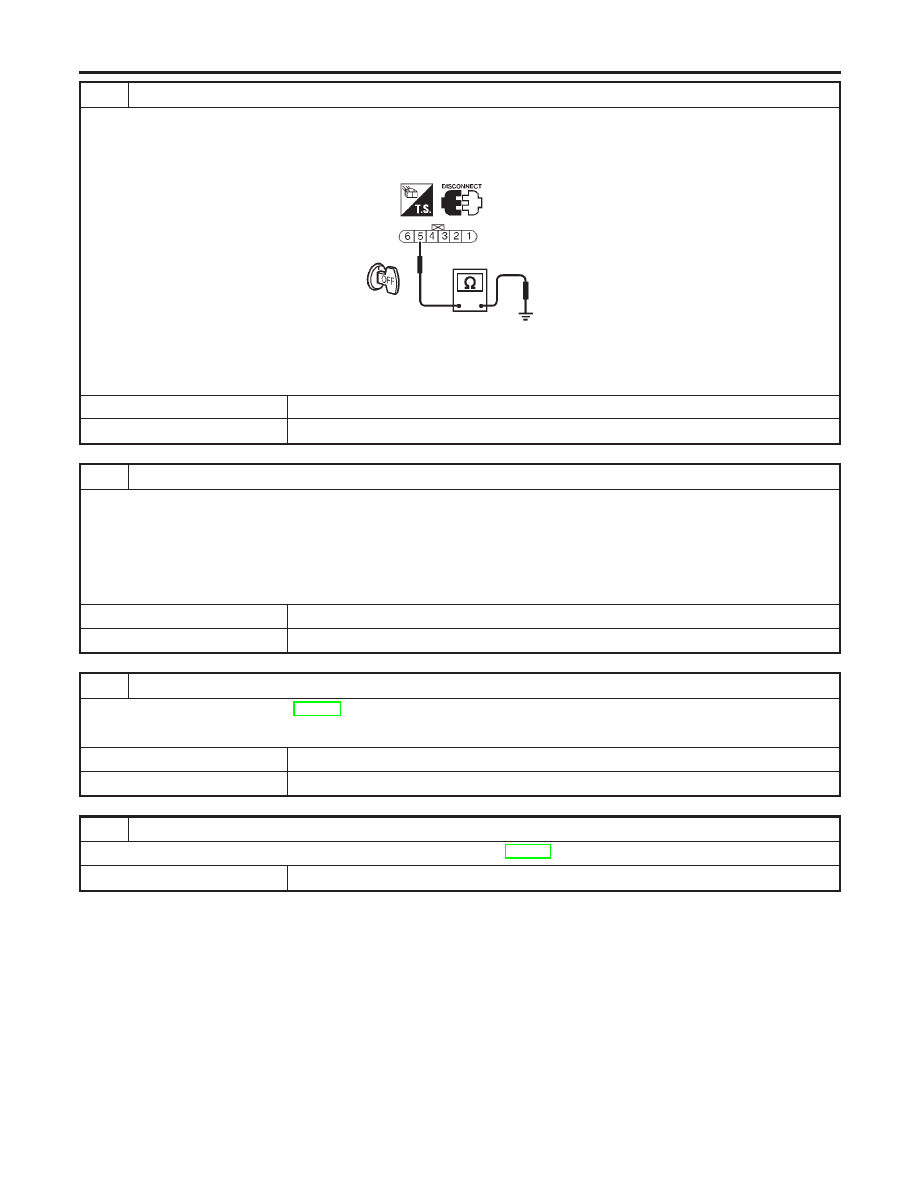
CHECK GROUND CIRCUIT
1. Turn ignition switch “OFF”.
2. Disconnect distributor harness connector.
3. Check harness continuity between terminal 5 and engine ground.
SEF258W
Continuity should exist.
4. Also check harness for short to power.
OK or NG
OK
©
GO TO 7.
NG
©
Repair open circuit or short to power in harness or connectors.
7
CHECK INPUT SIGNAL CIRCUIT-I
1. Disconnect ECM harness connector.
2. Check harness continuity between ECM terminal 35 and distributor terminal 6.
Refer to Wiring Diagram.
Continuity should exist.
3. Also check harness for short to ground and short to power.
OK or NG
OK
©
GO TO 8.
NG
©
Repair open circuit or short to ground or short to power in harness or connectors.
8
CHECK IGNITION COIL, POWER TRANSISTOR
Refer to “Component Inspection”, EC-595.
OK or NG
OK
©
GO TO 9.
NG
©
Replace malfunctioning component(s).
9
CHECK INTERMITTENT INCIDENT
Perform “TROUBLE DIAGNOSIS FOR INTERMITTENT INCIDENT”, EC-146.
©
INSPECTION END
IGNITION SIGNAL
Diagnostic Procedure (Cont’d)
EC-594
Нет комментариевНе стесняйтесь поделиться с нами вашим ценным мнением.
Текст