Infiniti G20 (P11). Manual — part 293
SEF740W
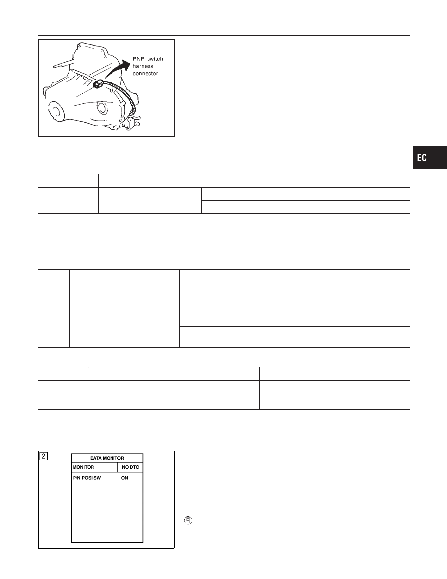
Component Description
NCEC0424
When the gear position is “P” (A/T models only) or “N”, park/neutral
position (PNP) switch is “ON”.
ECM detects the park/neutral position when continuity with ground
exists.
CONSULT-II Reference Value in Data Monitor
Mode
NCEC0425
Specification data are reference values.
MONITOR ITEM
CONDITION
SPECIFICATION
P/N POSI SW
I
Ignition switch: ON
Shift lever: “P” or “N”
ON
Except above
OFF
ECM Terminals and Reference Value
NCEC0426
Specification data are reference values and are measured between each terminal and ground.
CAUTION:
Do not use ECM ground terminals when measuring input/output voltage. Doing so may result in dam-
age to the ECM’s transistor. Use a ground other than ECM terminals, such as the ground.
TERMI-
NAL
NO.
WIRE
COLOR
ITEM
CONDITION
DATA (DC Voltage)
42
G/OR
PNP switch
[Ignition switch “ON”]
I
Gear position is “Neutral position” (M/T models)
I
Gear position is “N” or “P” (A/T models)
Approximately 0V
[Ignition switch “ON”]
I
Except the above gear position
BATTERY VOLTAGE
(11 - 14V)
On Board Diagnosis Logic
NCEC0427
DTC No.
Malfunction is detected when ...
Check Items (Possible Cause)
P1706
I
The signal of the PNP switch is not changed in the pro-
cess of engine starting and driving.
I
Harness or connectors
(The PNP switch circuit is open or shorted.)
I
PNP switch
SEF212Y
DTC Confirmation Procedure
NCEC0428
CAUTION:
Always drive vehicle at a safe speed.
NOTE:
If “DTC Confirmation Procedure” has been previously conducted,
always turn ignition switch “OFF” and wait at least 10 seconds
before conducting the next test.
With CONSULT-II
1)
Turn ignition switch “ON”.
GI
MA
EM
LC
FE
CL
MT
AT
AX
SU
BR
ST
RS
BT
HA
SC
EL
IDX
DTC P1706 PARK/NEUTRAL POSITION (PNP) SWITCH
Component Description
EC-583
SEF213Y
2)
Select “P/N POSI SW” in “DATA MONITOR” mode with CON-
SULT-II. Then check the “P/N POSI SW” signal under the fol-
lowing conditions.
Position (Selector lever)
Known-good signal
“N” and “P” (A/T only) position
ON
Except the above position
OFF
If NG, go to “Diagnostic Procedure”, EC-586.
If OK, go to following step.
3)
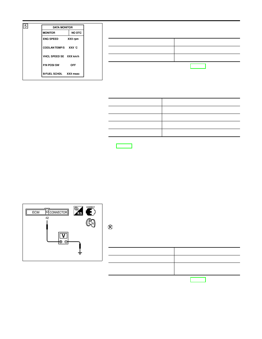
Select “DATA MONITOR” mode with CONSULT-II.
4)
Start engine and warm it up to normal operating temperature.
5)
Maintain the following conditions for at least 50 consecutive
seconds.
ENG SPEED
1,500 - 3,400 rpm
COOLAN TEMP/S
More than 70°C (158°F)
B/FUEL SCHDL
2.4 - 12 msec
VHCL SPEED SE
More than 64 km/h (40 MPH)
Selector lever
Suitable position
6)
If 1st trip DTC is detected, go to “Diagnostic Procedure”,
EC-586.
SEF137X
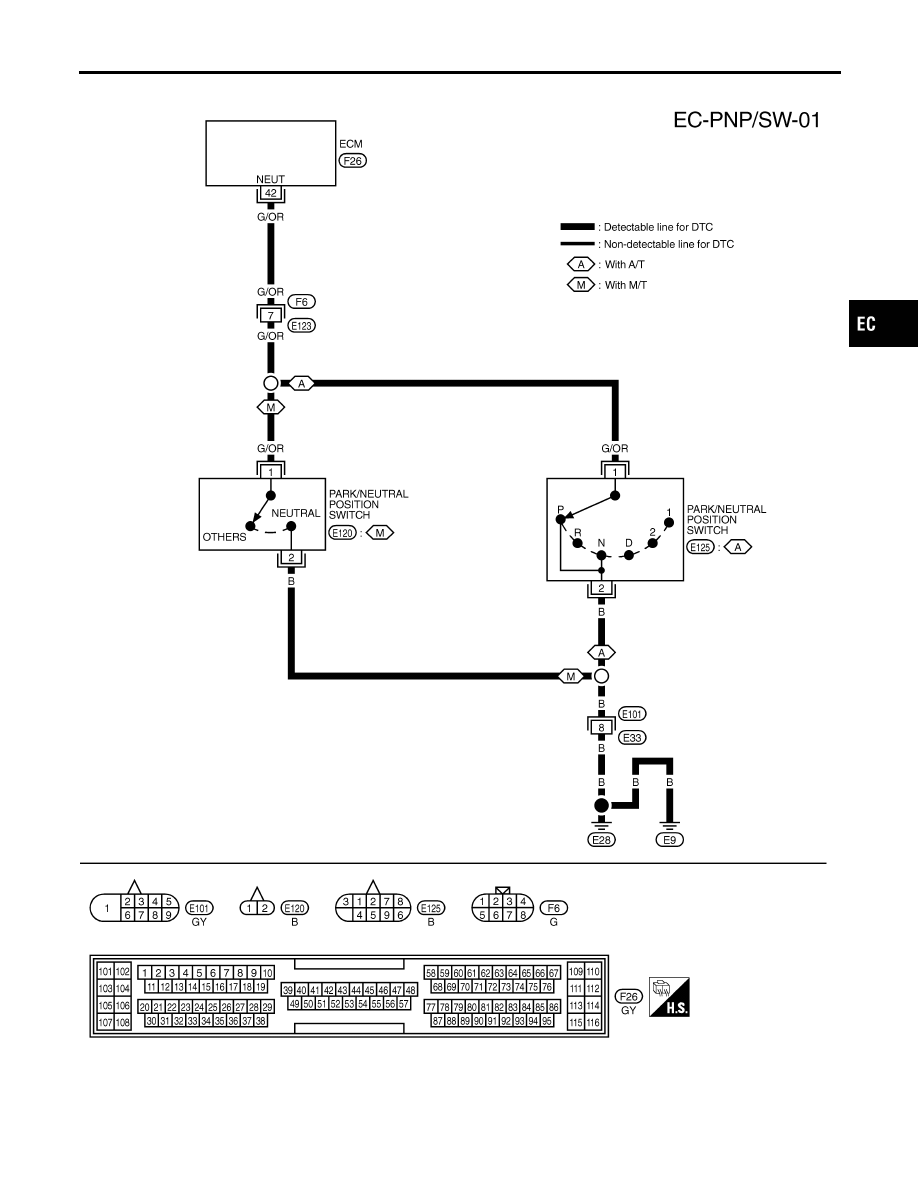
Overall Function Check
NCEC0429
Use this procedure to check the overall function of the park/neutral
position switch circuit. During this check, a 1st trip DTC might not
be confirmed.
Without CONSULT-II
1)
Turn ignition switch “ON”.
2)
Check voltage between ECM terminal 42 (PNP switch signal)
and body ground under the following conditions.
Condition (Gear position)
Voltage (V) (Known-good data)
“P” (A/T only) and “N” position
Approx. 0
Except the above position
BATTERY VOLTAGE
(11 - 14V)
3)
If NG, go to “Diagnostic Procedure”, EC-586.
DTC P1706 PARK/NEUTRAL POSITION (PNP) SWITCH
DTC Confirmation Procedure (Cont’d)
EC-584
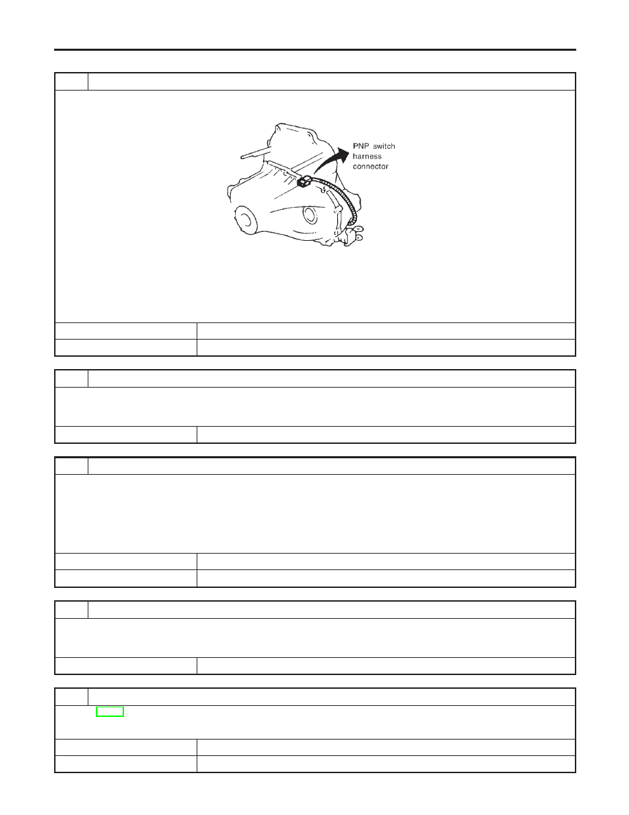
Wiring Diagram
NCEC0430
TEC722
GI
MA
EM
LC
FE
CL
MT
AT
AX
SU
BR
ST
RS
BT
HA
SC
EL
IDX
DTC P1706 PARK/NEUTRAL POSITION (PNP) SWITCH
Wiring Diagram
EC-585
Diagnostic Procedure For M/T Models
NCEC0431
1
CHECK GROUND CIRCUIT
1. Turn ignition switch “OFF”.
2. Disconnect PNP switch harness connector.
SEF740W
3. Check harness continuity between PNP switch terminal 2 and body ground.
Refer to Wiring Diagram.
Continuity should exist.
4. Also check harness for short to power.
OK or NG
OK
©
GO TO 3.
NG
©
GO TO 2.
2
DETECT MALFUNCTIONING PART
Check the following.
I
Harness connectors E101, E33
I
Harness for open or short between PNP switch and body ground
©
Repair open circuit or short to power in harness or connectors.
3
CHECK INPUT SIGNAL CIRCUIT
1. Disconnect ECM harness connector.
2. Check harness continuity between ECM terminal 42 and PNP switch terminal 1.
Refer to Wiring Diagram.
Continuity should exist.
3. Also check harness for short to ground and short to power.
OK or NG
OK
©
GO TO 5.
NG
©
GO TO 4.
4
DETECT MALFUNCTIONING PART
Check the following.
I
Harness connectors F6, E123
I
Harness for open or short between ECM and PNP switch
©
Repair open circuit or short to ground or short to power in harness or connectors.
5
CHECK PNP SWITCH
Refer to MT-10, “Position Switch Check”.
OK or NG
OK
©
GO TO 6.
NG
©
Replace PNP switch.
DTC P1706 PARK/NEUTRAL POSITION (PNP) SWITCH
Diagnostic Procedure For M/T Models
EC-586
Нет комментариевНе стесняйтесь поделиться с нами вашим ценным мнением.
Текст