Infiniti G20 (P11). Manual — part 294
6
CHECK INTERMITTENT INCIDENT
Perform “TROUBLE DIAGNOSIS FOR INTERMITTENT INCIDENT”, EC-146.
©
INSPECTION END
GI
MA
EM
LC
FE
CL
MT
AT
AX
SU
BR
ST
RS
BT
HA
SC
EL
IDX
DTC P1706 PARK/NEUTRAL POSITION (PNP) SWITCH
Diagnostic Procedure For M/T Models (Cont’d)
EC-587
Diagnostic Procedure For A/T Models
=NCEC0432
1
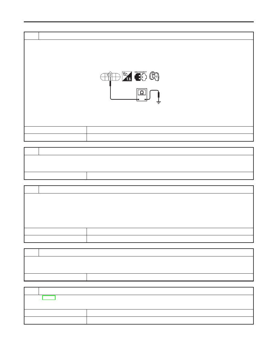
CHECK GROUND CIRCUIT
1. Turn ignition switch “OFF”.
2. Disconnect PNP switch harness connector.
3. Check continuity between PNP switch terminal 2 and ground with CONSULT-II or tester.
SEF269W
Continuity should exist.
4. Also check harness for short to power.
OK or NG
OK
©
GO TO 3.
NG
©
GO TO 2.
2
DETECT MALFUNCTIONING PART
Check the following.
I
Harness connectors E101, E33
I
Harness for open or short between PNP switch and body ground
©
Repair open circuit or short to power in harness or connectors.
3
CHECK INPUT SIGNAL CIRCUIT
1. Disconnect ECM harness connector.
2. Check harness continuity between ECM terminal 42 and PNP switch terminal 1.
Refer to Wiring Diagram.
Continuity should exist.
3. Also check harness for short to ground and short to power.
OK or NG
OK
©
GO TO 5.
NG
©
GO TO 4.
4
DETECT MALFUNCTIONING PART
Check the following.
I
Harness connectors F6, E123
I
Harness for open or short between PNP switch and ECM
©
Repair open circuit or short to ground or short to power in harness or connectors.
5
CHECK PNP SWITCH
Refer to AT-110, “Diagnostic Procedure”.
OK or NG
OK
©
GO TO 6.
NG
©
Replace PNP switch.
DTC P1706 PARK/NEUTRAL POSITION (PNP) SWITCH
Diagnostic Procedure For A/T Models
EC-588

6
CHECK INTERMITTENT INCIDENT
Perform “TROUBLE DIAGNOSIS FOR INTERMITTENT INCIDENT”, EC-146.
©
INSPECTION END
GI
MA
EM
LC
FE
CL
MT
AT
AX
SU
BR
ST
RS
BT
HA
SC
EL
IDX
DTC P1706 PARK/NEUTRAL POSITION (PNP) SWITCH
Diagnostic Procedure For A/T Models (Cont’d)
EC-589
SEF848X
Component Description
NCEC0319
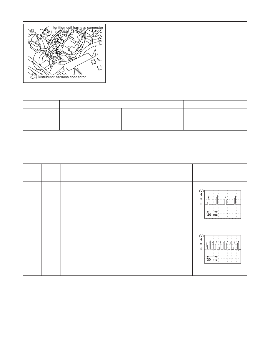
IGNITION COIL & POWER TRANSISTOR (BUILT INTO
DISTRIBUTOR)
NCEC0319S01
The ignition coil is built into distributor. The ignition signal from the
ECM is sent to the power transistor. The power transistor switches
on and off the ignition coil primary circuit. As the primary circuit is
turned on and off, the proper high voltage is induced in the coil
secondary circuit.
The distributor is not repairable and must be replaced as an
assembly except distributor cap and rotor head.
CONSULT-II Reference Value in Data Monitor
Mode
NCEC0320
MONITOR ITEM
CONDITION
SPECIFICATION
IGN TIMING
I
Engine: After warming up
I
Air conditioner switch: OFF
I
Shift lever: “N”
I
No-load
Idle
15°
±
2° BTDC
2,000 rpm
More than 25° BTDC
ECM Terminals and Reference Value
NCEC0321
Specification data are reference values and are measured between each terminal and ground.
CAUTION:
Do not use ECM ground terminals when measuring input/output voltage. Doing so may result in dam-
age to the ECM’s transistor. Use a ground other than ECM terminals, such as the ground.
TERMI-
NAL
NO.
WIRE
COLOR
ITEM
CONDITION
DATA (DC Voltage)
35
W/B
Ignition signal
[Engine is running]
I
Warm-up condition
I
Idle speed
Approximately 0.3V
SEF996V
[Engine is running]
I
Engine speed is 2,000 rpm
Approximately 0.5V
SEF997V
IGNITION SIGNAL
Component Description
EC-590
Нет комментариевНе стесняйтесь поделиться с нами вашим ценным мнением.
Текст