Infiniti G20 (P11). Manual — part 29
SAT283HB
SAT021J
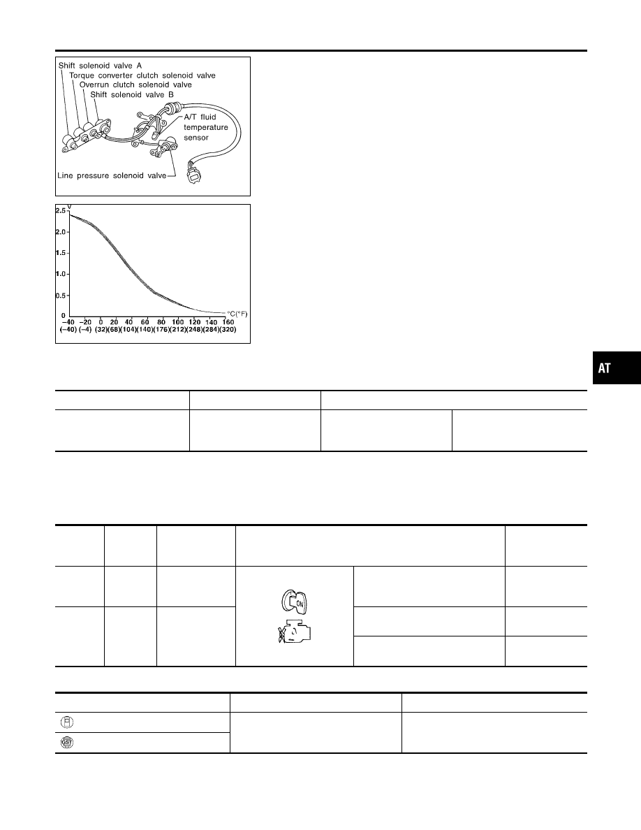
Description
NCAT0035
The A/T fluid temperature sensor detects the A/T fluid temperature
and sends a signal to the TCM.
CONSULT-II REFERENCE VALUE IN DATA MONITOR
MODE
NCAT0035S01
Remarks: Specification data are reference values.
Monitor item
Condition
Specification (Approximately)
A/T fluid temperature sensor
Cold [20°C (68°F)]
"
Hot [80°C (176°F)]
1.5V
"
0.5V
2.5 k
Ω
"
0.3 k
Ω
TCM TERMINALS AND REFERENCE VALUE
NCAT0035S02
Remarks: Specification data are reference values.
Terminal
No.
Wire color
Item
Condition
Judgement stan-
dard
(Approx.)
42
B
Throttle position
sensor
(Ground)
—
—
47
BR
A/T fluid tempera-
ture sensor
When ATF temperature is 20°C
(68°F).
1.5V
When ATF temperature is 80°C
(176°F).
0.5V
ON BOARD DIAGNOSIS LOGIC
NCAT0035S03
Diagnostic trouble code
Malfunction is detected when ...
Check items (Possible cause)
: ATF TEMP SEN/CIRC
TCM receives an excessively low or high
voltage from the sensor.
I
Harness or connectors
(The sensor circuit is open or shorted.)
I
A/T fluid temperature sensor
: P0710
GI
MA
EM
LC
EC
FE
CL
MT
AX
SU
BR
ST
RS
BT
HA
SC
EL
IDX
DTC P0710 A/T FLUID TEMPERATURE SENSOR CIRCUIT
Description
AT-113
SAT014K
SEF949Y
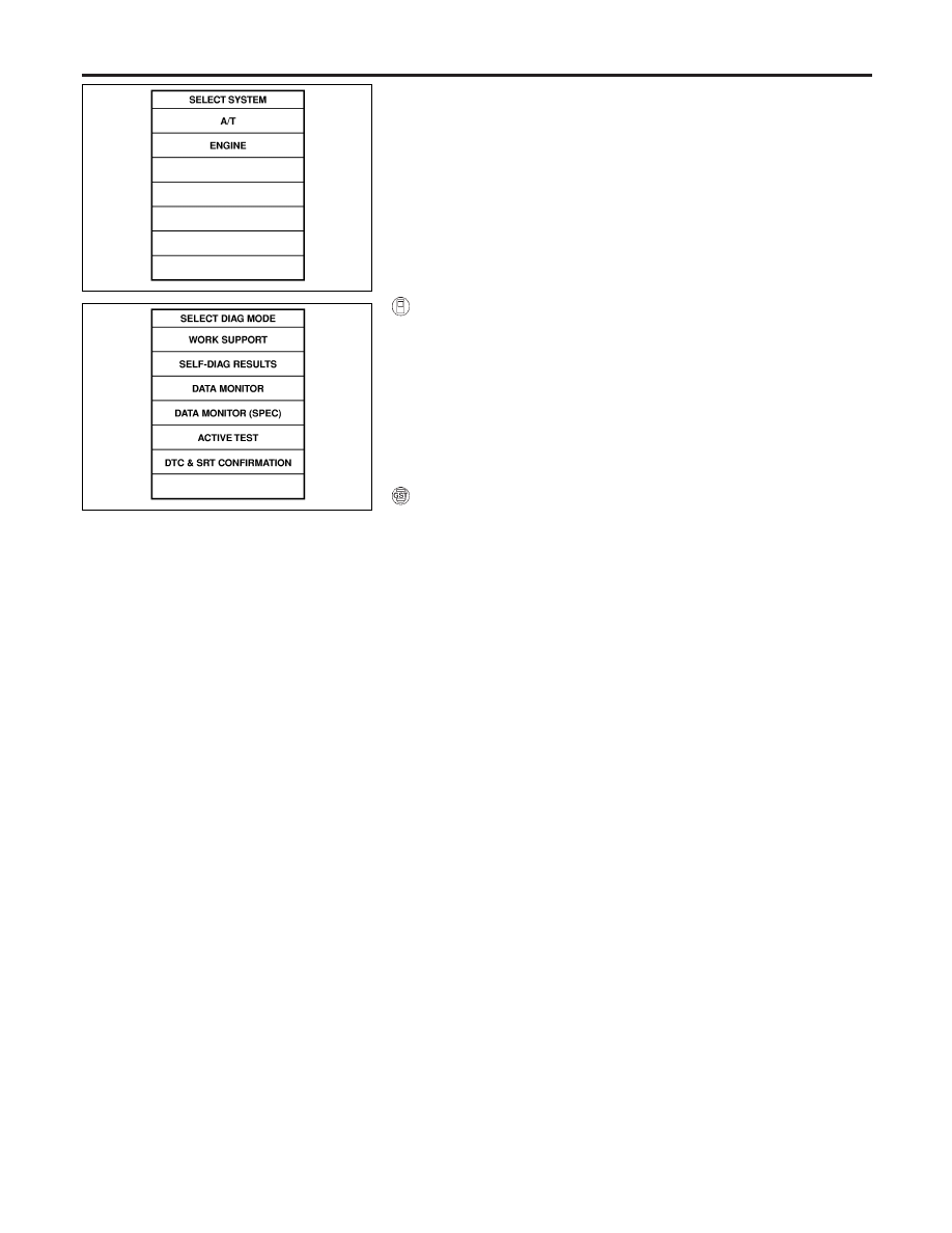
DIAGNOSTIC TROUBLE CODE (DTC) CONFIRMATION
PROCEDURE
NCAT0035S04
CAUTION:
Always drive vehicle at a safe speed.
NOTE:
If “DIAGNOSTIC TROUBLE CODE CONFIRMATION PROCE-
DURE” has been previously conducted, always turn ignition
switch “OFF” and wait at least 5 seconds before conducting
the next test.
After the repair, perform the following procedure to confirm the
malfunction is eliminated.
With CONSULT-II
1)
Turn ignition switch “ON” and select “DATA MONITOR” mode
for “ENGINE” with CONSULT-II.
2)
Start engine and maintain the following conditions for at least
10 minutes (Total). (It is not necessary to maintain continu-
ously.)
CMPS·RPM (REF): 450 rpm or more
VHCL SPEED SE: 10 km/h (6 MPH) or more
THRTL POS SEN: More than 1.2V
Selector lever: D position (OD “ON”)
With GST
Follow the procedure “With CONSULT-II”.
DTC P0710 A/T FLUID TEMPERATURE SENSOR CIRCUIT
Description (Cont’d)
AT-114
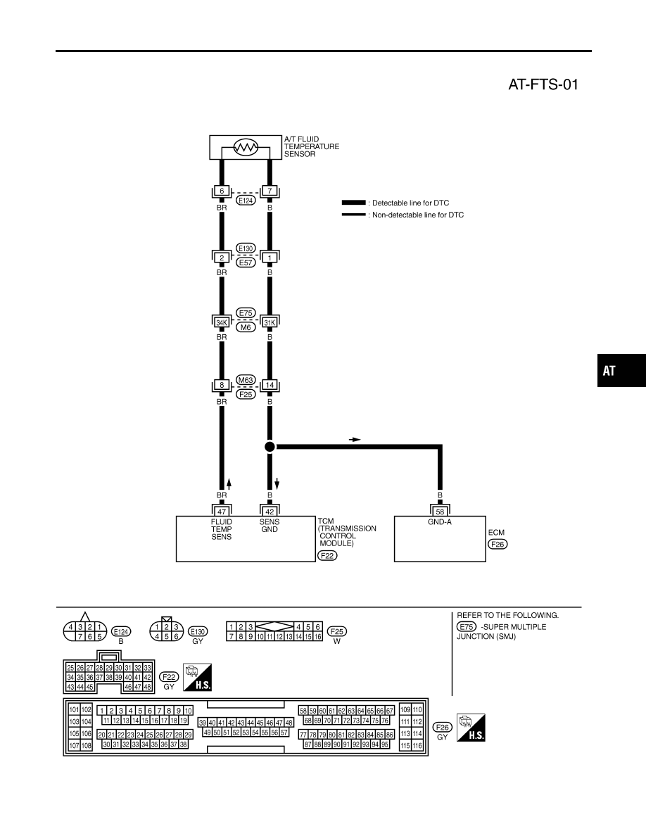
Wiring Diagram — AT — FTS
NCAT0200
TAT224
GI
MA
EM
LC
EC
FE
CL
MT
AX
SU
BR
ST
RS
BT
HA
SC
EL
IDX
DTC P0710 A/T FLUID TEMPERATURE SENSOR CIRCUIT
Wiring Diagram — AT — FTS
AT-115
Diagnostic Procedure
NCAT0036
1
INSPECTION START
Do you have CONSULT-II?
Yes or No
Yes
©
GO TO 2.
No
©
GO TO 3.
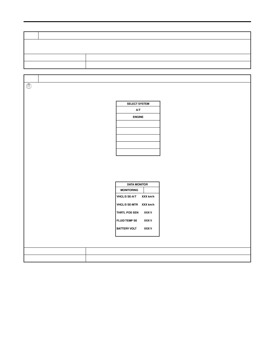
2
CHECK INPUT SIGNAL OF A/T FLUID TEMPERATURE SENSOR (With CONSULT-II)
With CONSULT-II
1. Start engine.
2. Select “TCM INPUT SIGNALS” in “DATA MONITOR” mode for “A/T” with CONSULT-II.
SAT014K
3. Read out the value of “FLUID TEMP SE”.
Voltage:
Cold [20°C (68°F)]
→
Hot [80°C (176°F)]:
Approximately 1.5V
→
0.5V
SAT614J
OK or NG
OK
©
GO TO 4.
NG
©
GO TO 5.
DTC P0710 A/T FLUID TEMPERATURE SENSOR CIRCUIT
Diagnostic Procedure
AT-116
Нет комментариевНе стесняйтесь поделиться с нами вашим ценным мнением.
Текст