Infiniti G20 (P11). Manual — part 28
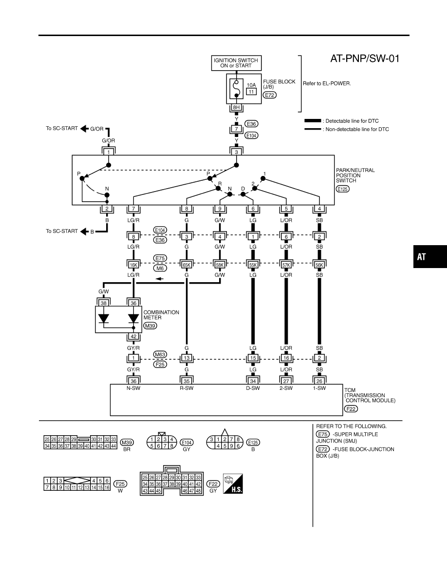
Wiring Diagram — AT — PNP/SW
NCAT0199
TAT270
GI
MA
EM
LC
EC
FE
CL
MT
AX
SU
BR
ST
RS
BT
HA
SC
EL
IDX
DTC P0705 PARK/NEUTRAL POSITION (PNP) SWITCH
Wiring Diagram — AT — PNP/SW
AT-109
Diagnostic Procedure
NCAT0033
1
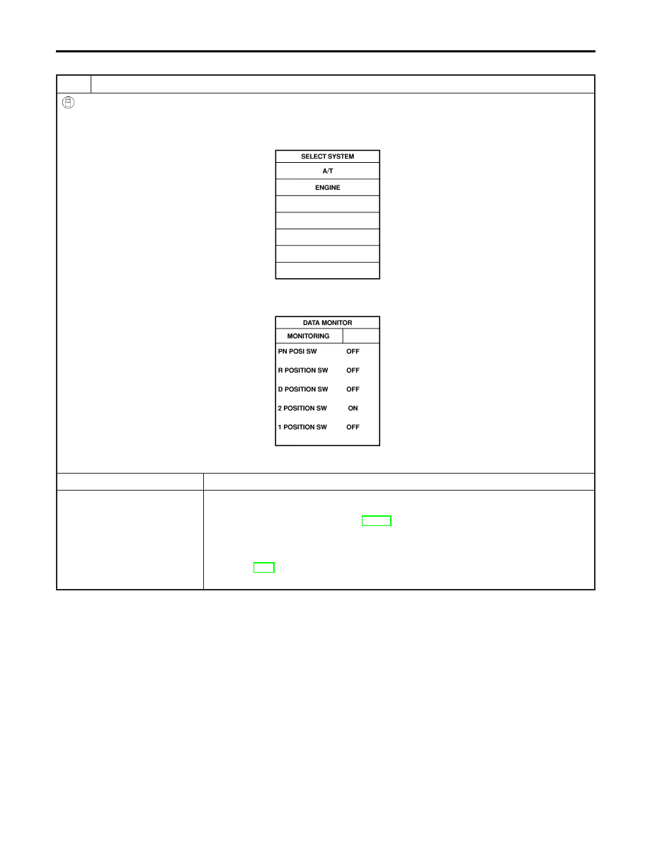
CHECK PNP SWITCH CIRCUIT (With CONSULT-II)
With CONSULT-II
1. Turn ignition switch to “ON” position.
(Do not start engine.)
2. Select “TCM INPUT SIGNALS” in “DATA MONITOR” mode for “A/T” with CONSULT-II.
SAT014K
3. Read out “P/N”, “R”, “D”, “2” and “1” position switches moving selector lever to each position.
Check the signal of the selector lever position is indicated properly.
SAT701J
OK or NG
OK
©
GO TO 3.
NG
©
Check the following items:
I
PNP switch
Refer to “Component Inspection”, AT-112.
I
Harness for short or open between ignition switch and PNP switch (Main harness)
I
Harness for short or open between PNP switch and TCM (Main harness)
I
Ignition switch and fuse
Refer to EL-9, “POWER SUPPLY ROUTING”.
I
Diode (P, N positions)
DTC P0705 PARK/NEUTRAL POSITION (PNP) SWITCH
Diagnostic Procedure
AT-110
2
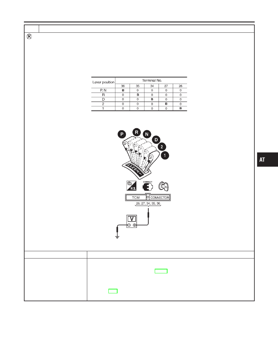
CHECK PNP SWITCH CIRCUIT (Without CONSULT-II)
Without CONSULT-II
1. Turn ignition switch to “ON” position.
(Do not start engine.)
2. Check voltage between TCM terminals 26, 27, 34, 35, 36 and ground while moving selector lever through each posi-
tion.
Voltage:
B: Battery voltage
0: 0V
MTBL0136
SAT425J
OK or NG
OK
©
GO TO 3.
NG
©
Check the following items:
I
PNP switch
Refer to “Component Inspection”, AT-112.
I
Harness for short or open between ignition switch and PNP switch (Main harness)
I
Harness for short or open between PNP switch and TCM (Main harness)
I
Ignition switch and fuse
Refer to EL-9, “POWER SUPPLY ROUTING”.
I
Diode (P, N positions)
GI
MA
EM
LC
EC
FE
CL
MT
AX
SU
BR
ST
RS
BT
HA
SC
EL
IDX
DTC P0705 PARK/NEUTRAL POSITION (PNP) SWITCH
Diagnostic Procedure (Cont’d)
AT-111
3
CHECK DTC
Perform Diagnostic Trouble Code (DTC) confirmation procedure, AT-108.
OK or NG
OK
©
INSPECTION END
NG
©
1. Perform TCM input/output signal inspection.
2. If NG, recheck TCM pin terminals for damage or loose connection with harness con-
nector.
SAT402J
Component Inspection
NCAT0034
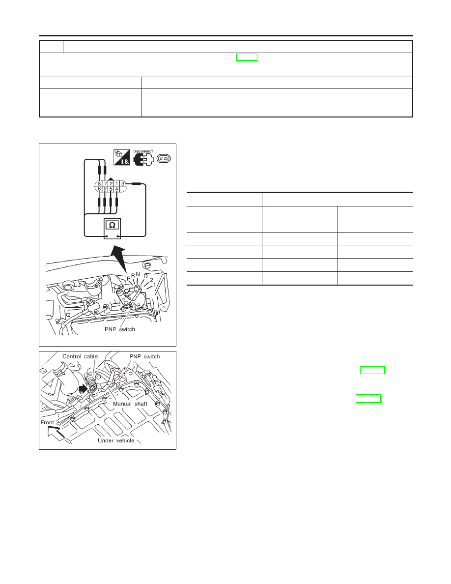
PARK/NEUTRAL POSITION SWITCH
NCAT0034S01
1.
Check continuity between terminals 1 and 3 and between ter-
minals 2 and 4, 5, 6, 7, 8, 9 while moving manual shaft through
each position.
Lever position
Terminal No.
P
3 — 7
1 — 2
R
3 — 8
N
3 — 9
1 — 2
D
3 — 6
2
3 — 5
1
3 — 4
SAT089JA
2.
If NG, check again with control cable disconnected from
manual shaft of A/T assembly. Refer to step 1.
3.
If OK on step 2, adjust control cable. Refer to AT-281.
4.
If NG on step 2, remove PNP switch from A/T and check con-
tinuity of PNP switch terminals. Refer to step 1.
5.
If OK on step 4, adjust PNP switch. Refer to AT-281.
6.
If NG on step 4, replace PNP switch.
DTC P0705 PARK/NEUTRAL POSITION (PNP) SWITCH
Diagnostic Procedure (Cont’d)
AT-112
Нет комментариевНе стесняйтесь поделиться с нами вашим ценным мнением.
Текст