Infiniti G20 (P11). Manual — part 27
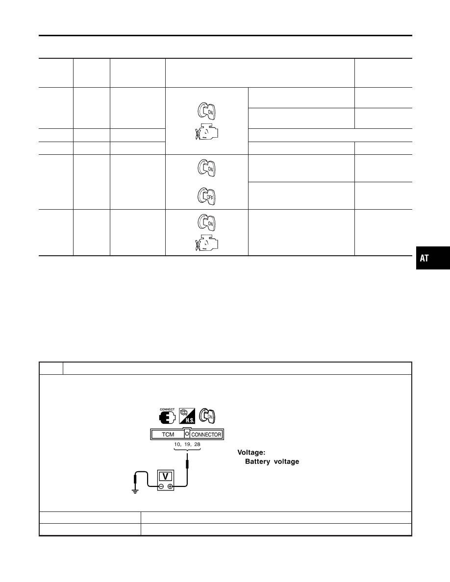
TCM TERMINALS AND REFERENCE VALUE
NCAT0031S01
Remarks: Specification data are reference values.
Terminal
No.
Wire color
Item
Condition
Judgement stan-
dard
(Approx.)
10
R
Power source
When turning ignition switch to
“ON”.
Battery voltage
When turning ignition switch to
“OFF”.
0V
19
R
Power source
Same as No. 10
25
B
Ground
—
—
28
P
Power source
(Memory back-up)
or
When turning ignition switch to
“OFF”.
Battery voltage
When turning ignition switch to
“ON”.
Battery voltage
48
B
Ground
—
—
Diagnostic Procedure
NCAT0228
1
CHECK TCM POWER SOURCE STEP 1
1. Turn ignition switch to ON position.
(Do not start engine.)
2. Check voltage between TCM terminals 10, 19, 28 and ground.
SAT611J
OK or NG
OK
©
GO TO 2.
NG
©
GO TO 3.
GI
MA
EM
LC
EC
FE
CL
MT
AX
SU
BR
ST
RS
BT
HA
SC
EL
IDX
TROUBLE DIAGNOSIS FOR POWER SUPPLY
Wiring Diagram — AT — MAIN (Cont’d)
AT-105
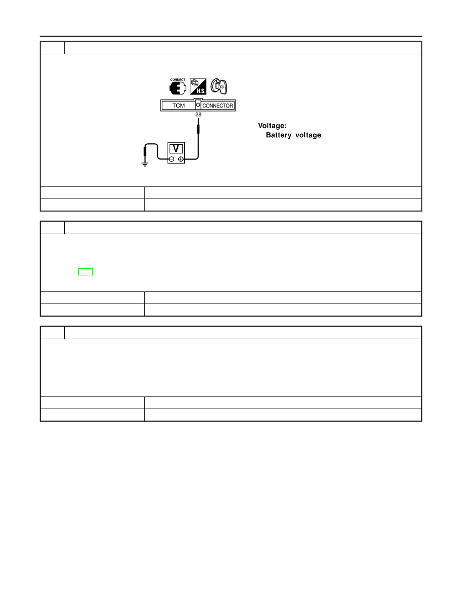
2
CHECK TCM POWER SOURCE STEP 2
1. Turn ignition switch to OFF position.
2. Check voltage between TCM terminal 28 and ground.
SAT612JD
OK or NG
OK
©
GO TO 4.
NG
©
GO TO 3.
3
DETECT MALFUNCTIONING ITEM
Check the following items:
I
Harness for short or open between ignition switch and TCM terminals 10, 19 and 28 (Main harness)
I
Fuse
I
Ignition switch
Refer to EL-9, “POWER SUPPLY ROUTING”.
OK or NG
OK
©
GO TO 4.
NG
©
Repair or replace damaged parts.
4
CHECK TCM GROUND CIRCUIT
1. Turn ignition switch to OFF position.
2. Disconnect TCM harness connector.
3. Check continuity between TCM terminals 25, 48 and ground. Refer to wiring diagram — AT — MAIN.
Continuity should exist.
If OK, check harness for short to ground and short to power.
OK or NG
OK
©
INSPECTION END
NG
©
Repair open circuit or short to ground or short to power in harness or connectors.
TROUBLE DIAGNOSIS FOR POWER SUPPLY
Diagnostic Procedure (Cont’d)
AT-106
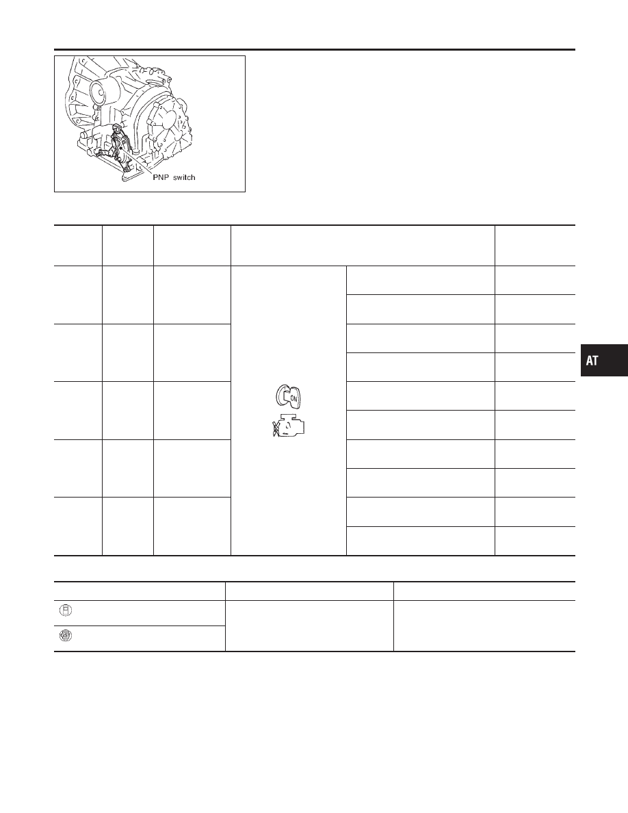
SAT088JA
Description
NCAT0032
I
The PNP switch assembly includes a transmission range
switch.
I
The transmission range switch detects the selector lever posi-
tion and sends a signal to the TCM.
TCM TERMINALS AND REFERENCE VALUE
NCAT0032S01
Remarks: Specification data are reference values.
Terminal
No.
Wire color
Item
Condition
Judgement stan-
dard
(Approx.)
26
SB
PNP switch “1”
position
When setting selector lever to “1”
position.
Battery voltage
When setting selector lever to other
positions.
0V
27
L/OR
PNP switch “2”
position
When setting selector lever to “2”
position.
Battery voltage
When setting selector lever to other
positions.
0V
34
LG
PNP switch “D”
position
When setting selector lever to “D”
position.
Battery voltage
When setting selector lever to other
positions.
0V
35
G
PNP switch “R”
position
When setting selector lever to “R”
position.
Battery voltage
When setting selector lever to other
positions.
0V
36
GY/R
PNP switch “N” or
“P” position
When setting selector lever to “N” or
“P” position.
Battery voltage
When setting selector lever to other
positions.
0V
ON BOARD DIAGNOSIS LOGIC
NCAT0032S02
Diagnostic trouble code
Malfunction is detected when ...
Check items (Possible cause)
: PNP SW/CIRC
TCM does not receive the correct voltage
signal from the switch based on the gear
position.
I
Harness or connectors
(The PNP switch circuit is open or
shorted.)
I
PNP switch
: P0705
GI
MA
EM
LC
EC
FE
CL
MT
AX
SU
BR
ST
RS
BT
HA
SC
EL
IDX
DTC P0705 PARK/NEUTRAL POSITION (PNP) SWITCH
Description
AT-107
SAT014K
SEF949Y
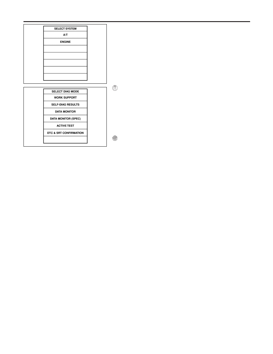
DIAGNOSTIC TROUBLE CODE (DTC) CONFIRMATION
PROCEDURE
NCAT0032S03
CAUTION:
Always drive vehicle at a safe speed.
NOTE:
If “DIAGNOSTIC TROUBLE CODE CONFIRMATION PROCE-
DURE” has been previously conducted, always turn ignition
switch “OFF” and wait at least 5 seconds before conducting
the next test.
After the repair, perform the following procedure to confirm the
malfunction is eliminated.
With CONSULT-II
1)
Turn ignition switch “ON”.
2)
Select “DATA MONITOR” mode for “ENGINE” with CONSULT-
II.
3)
Start engine and maintain the following conditions for at least
5 consecutive seconds.
VHCL SPEED SE: 10 km/h (6 MPH) or more
THRTL POS SEN: More than 1.3V
Selector lever: D position (OD “ON” or “OFF”)
With GST
Follow the procedure “With CONSULT-II”.
DTC P0705 PARK/NEUTRAL POSITION (PNP) SWITCH
Description (Cont’d)
AT-108
Нет комментариевНе стесняйтесь поделиться с нами вашим ценным мнением.
Текст