Infiniti G20 (P11). Manual — part 297
2
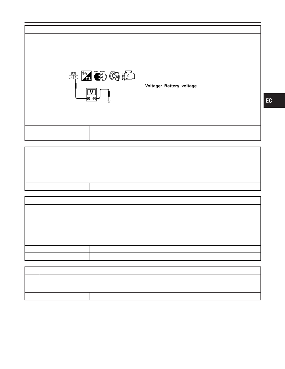
CHECK POWER SUPPLY
1. Stop engine.
2. Disconnect injector harness connector.
3. Turn ignition switch “ON”.
4. Check voltage between injector terminal 1 and ground with CONSULT-II or tester.
SEF949X
OK or NG
OK
©
GO TO 4.
NG
©
GO TO 3.
3
DETECT MALFUNCTIONING PART
Check the following.
I
10A fuse
I
Harness connectors M62, F24
I
Harness connectors F13, F51
I
Harness for open or short between injector and fuse
©
Repair harness or connectors.
4
CHECK OUTPUT SIGNAL CIRCUIT
1. Turn ignition switch “OFF”.
2. Disconnect ECM harness connector.
3. Check harness continuity between injector harness connector terminal 2 and ECM terminals 101, 103, 105, 107.
Refer to Wiring Diagram.
Continuity should exist.
4. Also check harness for short to ground and short to power.
OK or NG
OK
©
GO TO 6.
NG
©
GO TO 5.
5
DETECT MALFUNCTIONING PART
Check the following.
I
Harness connectors F51, F13
I
Harness for open or short between ECM and injector
©
Repair open circuit or short to ground or short to power in harness or connectors.
GI
MA
EM
LC
FE
CL
MT
AT
AX
SU
BR
ST
RS
BT
HA
SC
EL
IDX
INJECTOR
Diagnostic Procedure (Cont’d)
EC-599
6
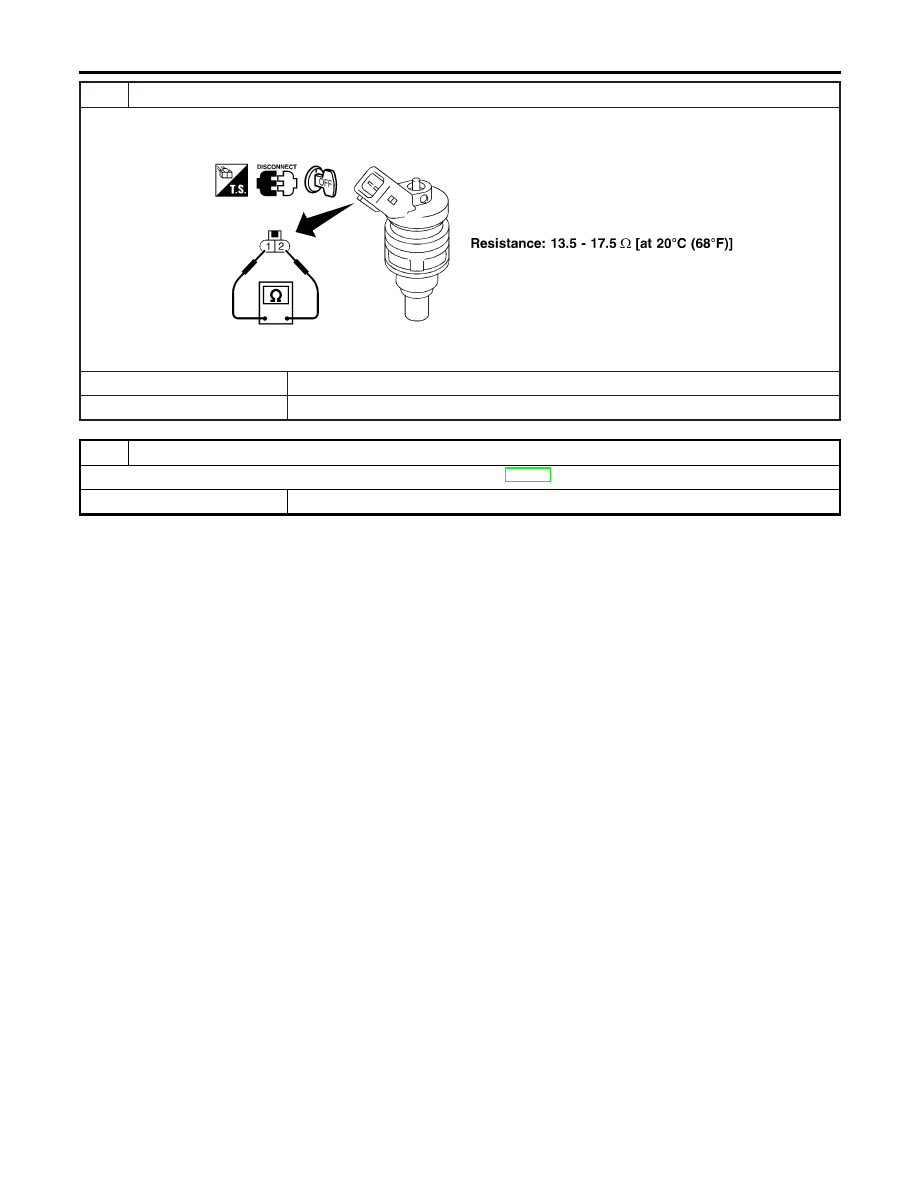
CHECK INJECTOR
1. Disconnect injector harness connector.
2. Check resistance between terminals as shown in the figure.
SEF964XA
OK or NG
OK
©
GO TO 7.
NG
©
Replace injector.
7
CHECK INTERMITTENT INCIDENT
Perform “TROUBLE DIAGNOSIS FOR INTERMITTENT INCIDENT”, EC-146.
©
INSPECTION END
INJECTOR
Diagnostic Procedure (Cont’d)
EC-600
CONSULT-II Reference Value in Data Monitor
Mode
NCEC0441
Specification data are reference values.
MONITOR ITEM
CONDITION
SPECIFICATION
START SIGNAL
I
Ignition switch: ON
,
START
,
ON
OFF
,
ON
,
OFF
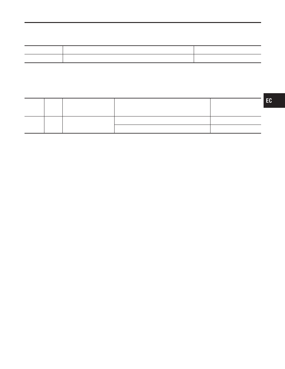
ECM Terminals and Reference Value
NCEC0442
Specification data are reference values and are measured between each terminal and ground.
CAUTION:
Do not use ECM ground terminals when measuring input/output voltage. Doing so may result in dam-
age to the ECM’s transistor. Use a ground other than ECM terminals, such as the ground.
TERMI-
NAL
NO.
WIRE
COLOR
ITEM
CONDITION
DATA (DC Voltage)
41
B/Y
Start signal
[Ignition switch “ON”]
Approximately 0V
[Ignition switch “START”]
9 - 14V
GI
MA
EM
LC
FE
CL
MT
AT
AX
SU
BR
ST
RS
BT
HA
SC
EL
IDX
START SIGNAL
CONSULT-II Reference Value in Data Monitor Mode
EC-601
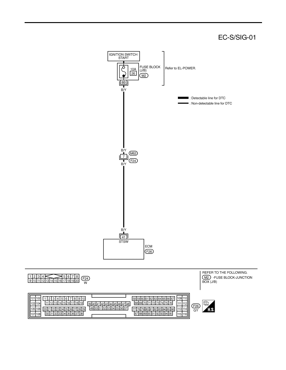
Wiring Diagram
NCEC0440
TEC725
START SIGNAL
Wiring Diagram
EC-602
Нет комментариевНе стесняйтесь поделиться с нами вашим ценным мнением.
Текст