Infiniti G20 (P11). Manual — part 298
Diagnostic Procedure
=NCEC0443
1
INSPECTION START
Do you have CONSULT-II?
Yes or No
Yes
©
GO TO 2.
No
©
GO TO 3.
2
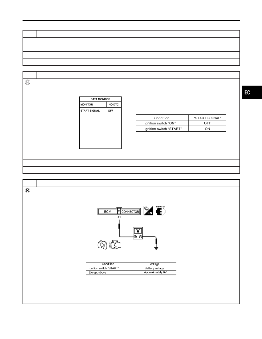
CHECK OVERALL FUNCTION
With CONSULT-II
1. Turn ignition switch “ON”.
2. Check “START SIGNAL” in “DATA MONITOR” mode with CONSULT-II under the following conditions.
SEF227Y
OK or NG
OK
©
INSPECTION END
NG
©
GO TO 4.
3
CHECK OVERALL FUNCTION
Without CONSULT-II
1. Turn ignition switch to “START”.
2. Check voltage between ECM terminal 41 and ground under the following conditions.
SEF142X
MTBL0143
OK or NG
OK
©
INSPECTION END
NG
©
GO TO 4.
GI
MA
EM
LC
FE
CL
MT
AT
AX
SU
BR
ST
RS
BT
HA
SC
EL
IDX
START SIGNAL
Diagnostic Procedure
EC-603
4
DETECT MALFUNCTIONING PART
Check the following.
I
Harness connectors M62, F24
I
10A fuse
I
Harness for open or short between ECM and fuse
OK or NG
OK
©
GO TO 5.
NG
©
Repair open circuit or short to ground or short to power in harness or connectors.
5
CHECK INTERMITTENT INCIDENT
Perform “TROUBLE DIAGNOSIS FOR INTERMITTENT INCIDENT”, EC-146.
©
INSPECTION END
START SIGNAL
Diagnostic Procedure (Cont’d)
EC-604
System Description
NCEC0444
Sensor
Input Signal to ECM
ECM func-
tion
Actuator
Camshaft position sensor
Engine speed
ECM
Fuel pump relay
Ignition switch
Start signal
The ECM activates the fuel pump for several seconds after the ignition switch is turned on to improve engine
startability. If the ECM receives a 180° signal from the camshaft position sensor, it knows that the engine is
rotating, and causes the pump to perform. If the 180° signal is not received when the ignition switch is on, the
engine stalls. The ECM stops pump operation and prevents battery discharging, thereby improving safety. The
ECM does not directly drive the fuel pump. It controls the ON/OFF fuel pump relay, which in turn controls the
fuel pump.
Condition
Fuel pump operation
Ignition switch is turned to ON.
Operates for 5 seconds
Engine running and cranking
Operates
When engine is stopped
Stops in 1 second
Except as shown above
Stops
AEC801
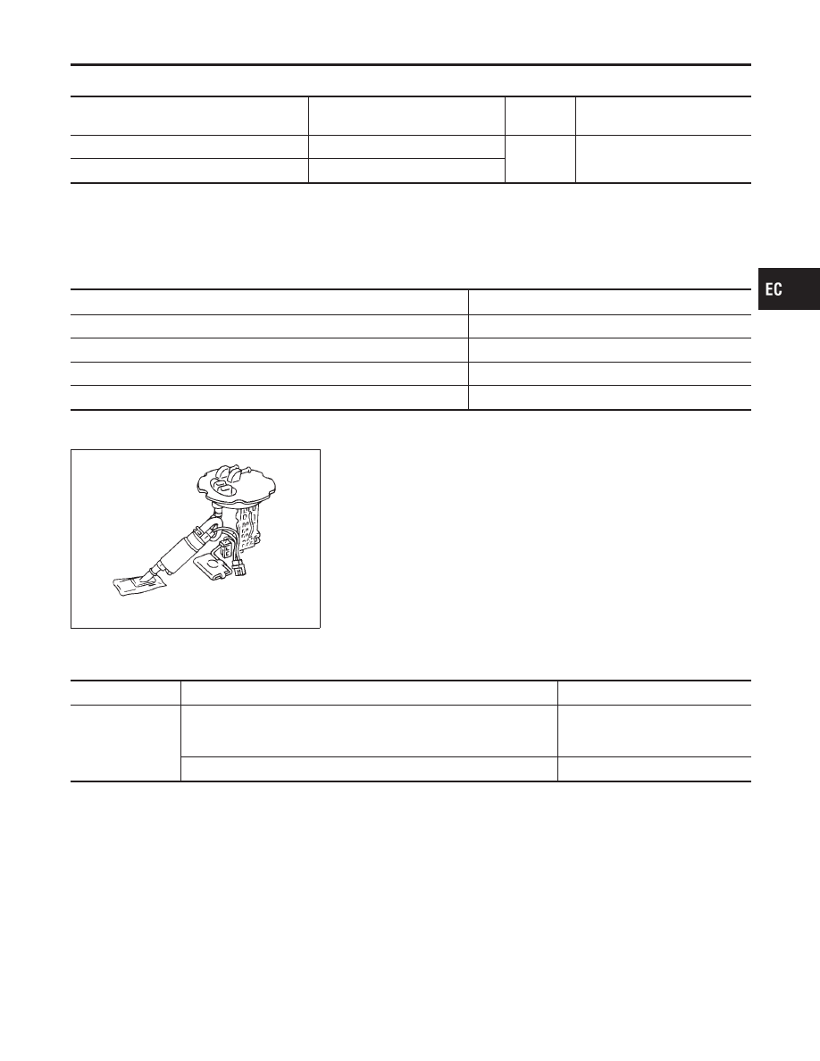
Component Description
NCEC0501
A turbine type design fuel pump is used in the fuel tank.
CONSULT-II Reference Value in Data Monitor
Mode
NCEC0445
MONITOR ITEM
CONDITION
SPECIFICATION
FUEL PUMP RLY
I
Ignition switch is turned to ON (Operates for 5 seconds)
I
Engine running and cranking
I
When engine is stopped (stops in 1.0 seconds)
ON
I
Except as shown above
OFF
GI
MA
EM
LC
FE
CL
MT
AT
AX
SU
BR
ST
RS
BT
HA
SC
EL
IDX
FUEL PUMP
System Description
EC-605

ECM Terminals and Reference Value
=NCEC0446
Specification data are reference values and are measured between each terminal and ground.
CAUTION:
Do not use ECM ground terminals when measuring input/output voltage. Doing so may result in dam-
age to the ECM’s transistor. Use a ground other than ECM terminals, such as the ground.
TERMI-
NAL
NO.
WIRE
COLOR
ITEM
CONDITION
DATA (DC Voltage)
21
B/P
Fuel pump relay
[Ignition switch “ON”]
I
For 5 seconds after turning ignition switch “ON”
[Engine is running]
0 - 1V
[Ignition switch “ON”]
I
More than 5 seconds after turning ignition switch
“ON”
BATTERY VOLTAGE
(11 - 14V)
FUEL PUMP
ECM Terminals and Reference Value
EC-606
Нет комментариевНе стесняйтесь поделиться с нами вашим ценным мнением.
Текст