Infiniti QX56 (JA60). Manual — part 234
INTELLIGENT KEY BATTERY AND FUNCTION
DLK-107
< COMPONENT DIAGNOSIS >
[WITH INTELLIGENT KEY SYSTEM]
C
D
E
F
G
H
I
J
L
M
A
B
DLK
N
O
P
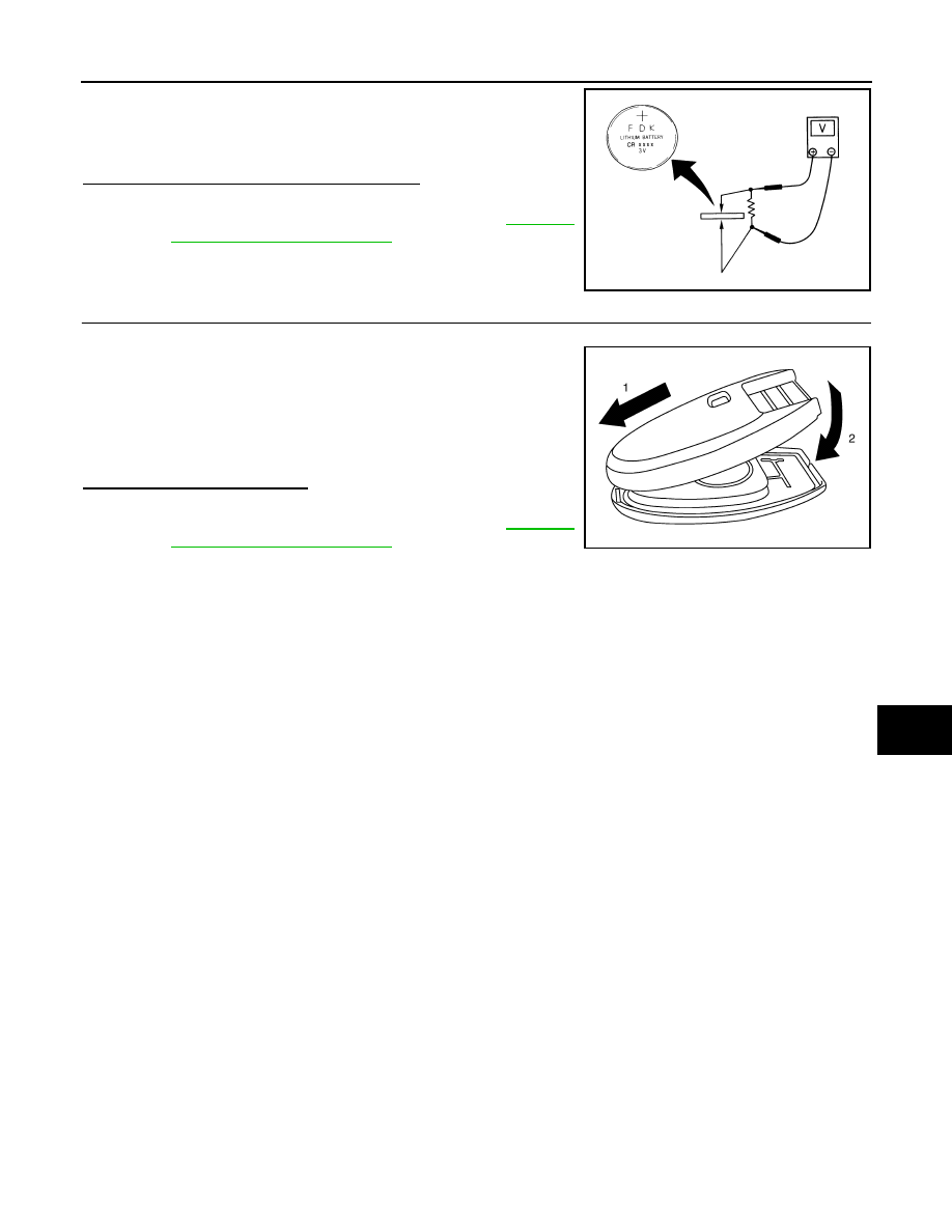
Check by connecting a resistance (approximately 300
Ω) so that the
current value becomes about 10 mA.
Is the measurement value within specification?
YES
>> Intelligent Key battery is OK. Check remote keyless
entry receiver. Refer to
NO
>> GO TO 4
4.
REPLACE INTELLIGENT KEY BATTERY
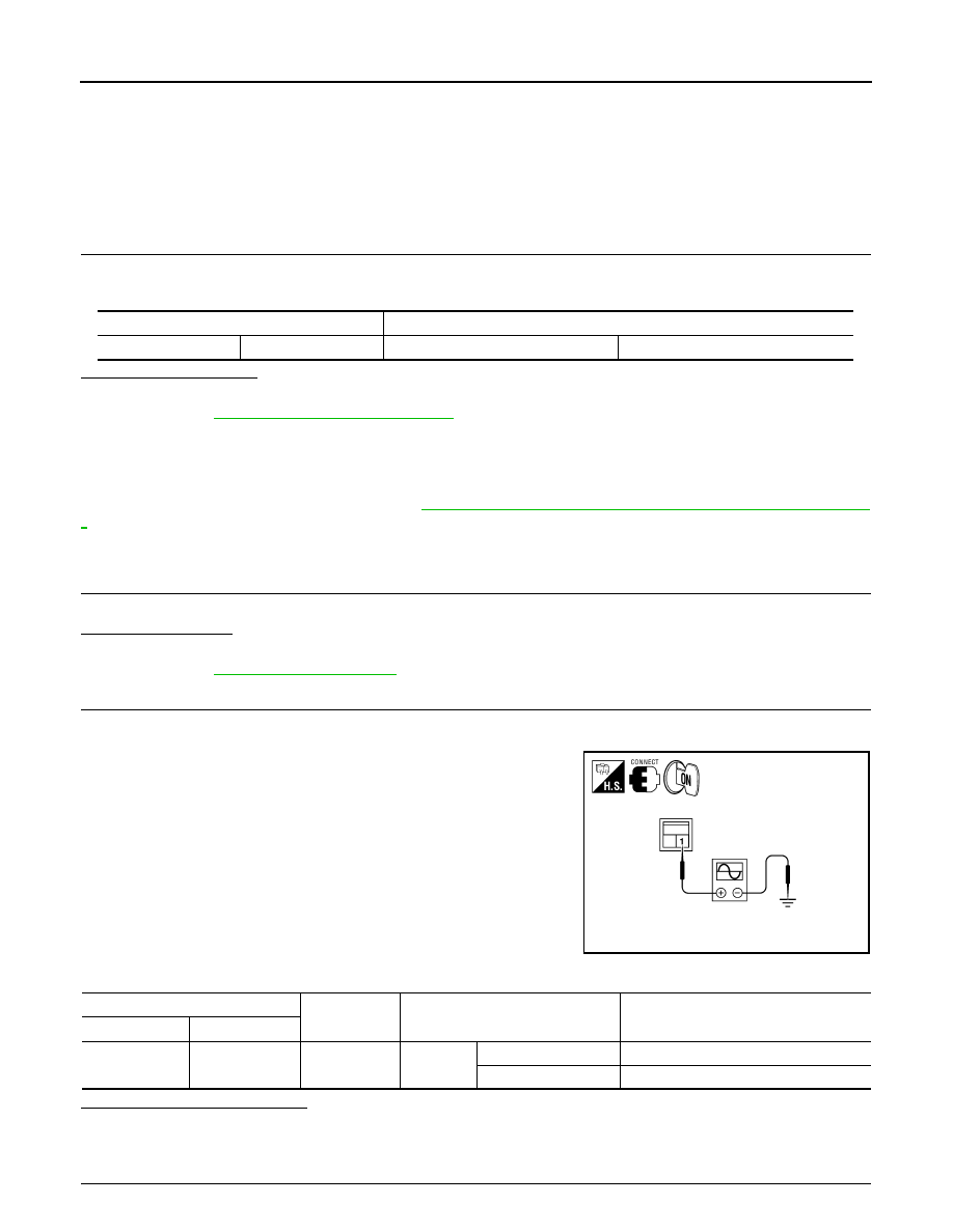
1. Replace the Intelligent Key battery.
2. Align the tips of the upper and lower parts, and then push them
together until it is securely closed.
CAUTION:
• When replacing battery, keep dirt, grease, and other for-
eign materials off the electrode contact area.
3. After replacing the battery, check that all Intelligent Key func-
tions work properly.
Is the inspection result normal?
YES
>> Intelligent Key is OK.
NO
>> Check remote keyless entry receiver. Refer to
Standard
: Approx. 2.5 - 3.0V
OCC0607D
PIIB6222E
DLK-108
< COMPONENT DIAGNOSIS >
[WITH INTELLIGENT KEY SYSTEM]
HORN FUNCTION
HORN FUNCTION
Description
INFOID:0000000005146978
Perform answer-back for each operation with horn.
Component Function Check
INFOID:0000000005146979
1.
CHECK FUNCTION
1. Select "HORN" in “ACTIVE TEST” mode with CONSULT-III.
2. Check the horn (high/low) operation.
Is the operation normal?
YES
>> Inspection End.
NO
>> Go to
DLK-108, "Diagnosis Procedure"
.
Diagnosis Procedure
INFOID:0000000005146980
Regarding Wiring Diagram information, refer to
DLK-178, "Wiring Diagram — INTELLIGENT KEY SYSTEM —
1.
CHECK HORN FUNCTION
Check horn function with horn switch
Do the horns sound?
YES
>> GO TO 2
NO
>> Go to
.
2.
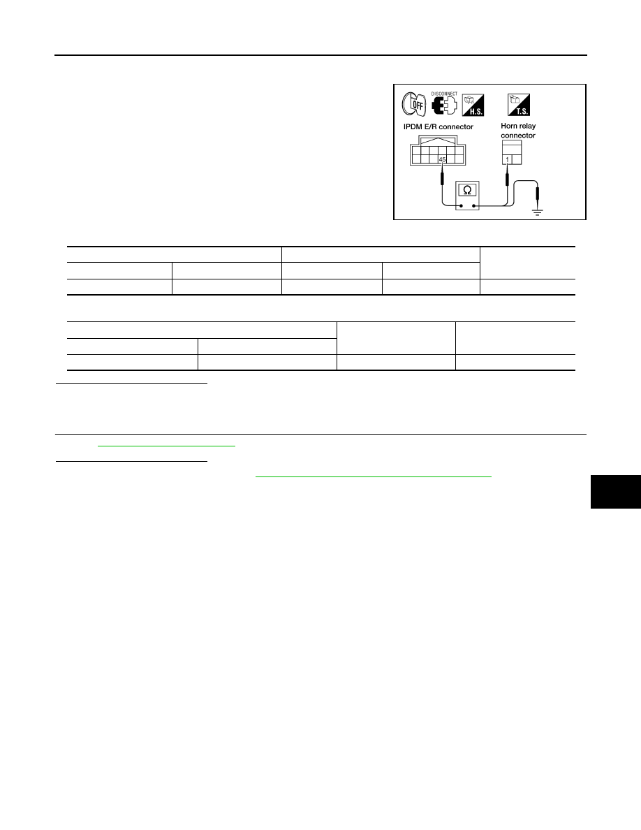
CHECK HORN RELAY POWER SUPPLY
1. Turn ignition switch ON.
2. Perform “ACTIVE TEST”, "HORN" with CONSULT-Ill.
3. Using an oscilloscope or analog voltmeter, check voltage
between horn relay harness connector and ground.
Is the inspection result normal?
YES
>> GO TO 4
NO
>> GO TO 3
3.
CHECK HORN RELAY CIRCUIT
Test item
Description
HORN
ON
Horn relay
ON (for 20 ms)
ALKIA0658ZZ
Horn relay
Ground
Test item
Voltage (V)
(Approx.)
Connector
Terminal
H-1
1
Ground
HORN
ON
Battery voltage
→ 0 → Battery voltage
Other than above
Battery voltage
HORN FUNCTION
DLK-109
< COMPONENT DIAGNOSIS >
[WITH INTELLIGENT KEY SYSTEM]
C
D
E
F
G
H
I
J
L
M
A
B
DLK
N
O
P
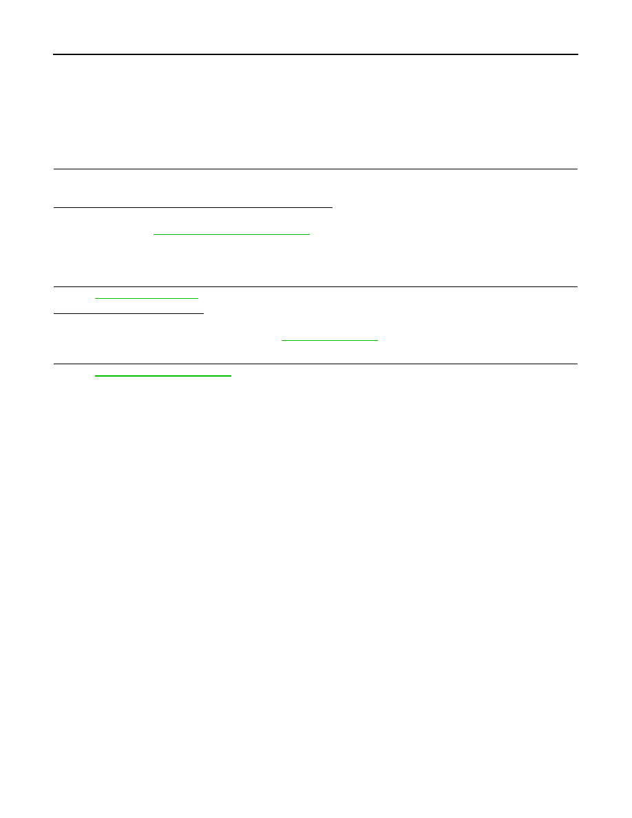
1. Turn ignition switch OFF.
2. Disconnect IPDM E/R and horn relay connector.
3. Check continuity between IPDM E/R harness connector and
horn relay harness connector.
4. Check continuity between IPDM E/R harness connector and ground.
Is the inspection result normal?
YES
>> GO TO 4
NO
>> Repair or replace harness.
4.
CHECK INTERMITTENT INCIDENT
GI-38, "Intermittent Incident"
.
Is the inspection result normal?
YES
>> Replace IPDM E/R. Refer to
PCS-35, "Removal and Installation of IPDM E/R"
.
NO
>> Repair or replace the malfunctioning part.
WIIA0679E
IPDM E/R
Horn relay
Continuity
Connector
Terminal
Connector
Terminal
E122
45
H-1
1
Yes
IPDM E/R
Ground
Continuity
Connector
Terminal
E122
45
Ground
No
DLK-110
< COMPONENT DIAGNOSIS >
[WITH INTELLIGENT KEY SYSTEM]
COMBINATION METER DISPLAY FUNCTION
COMBINATION METER DISPLAY FUNCTION
Description
INFOID:0000000005146981
Displays each operation method guide and warning for system malfunction.
Component Function Check
INFOID:0000000005146982
1.
CHECK FUNCTION
1. Turn ignition switch ON.
2. Open driver door.
Does the open door message appear on the LCD display?
YES
>> Meter information display is OK.
NO
>> Refer to
DLK-110, "Diagnosis Procedure"
Diagnosis Procedure
INFOID:0000000005146983
1.
CHECK COMBINATION METER
.
Is the inspection result normal?
YES
>> GO TO 2
NO
>> Check combination meter. Refer to
.
2.
CHECK INTERMITTENT INCIDENT
GI-38, "Intermittent Incident"
>> Inspection End.
Нет комментариевНе стесняйтесь поделиться с нами вашим ценным мнением.
Текст