Infiniti QX56 (JA60). Manual — part 232
STEERING LOCK UNIT
DLK-99
< COMPONENT DIAGNOSIS >
[WITH INTELLIGENT KEY SYSTEM]
C
D
E
F
G
H
I
J
L
M
A
B
DLK
N
O
P
STEERING LOCK UNIT
Diagnosis Procedure
INFOID:0000000005146970
Regarding Wiring Diagram information, refer to
DLK-178, "Wiring Diagram — INTELLIGENT KEY SYSTEM —
1.
CHECK STEERING LOCK SOLENOID POWER SUPPLY
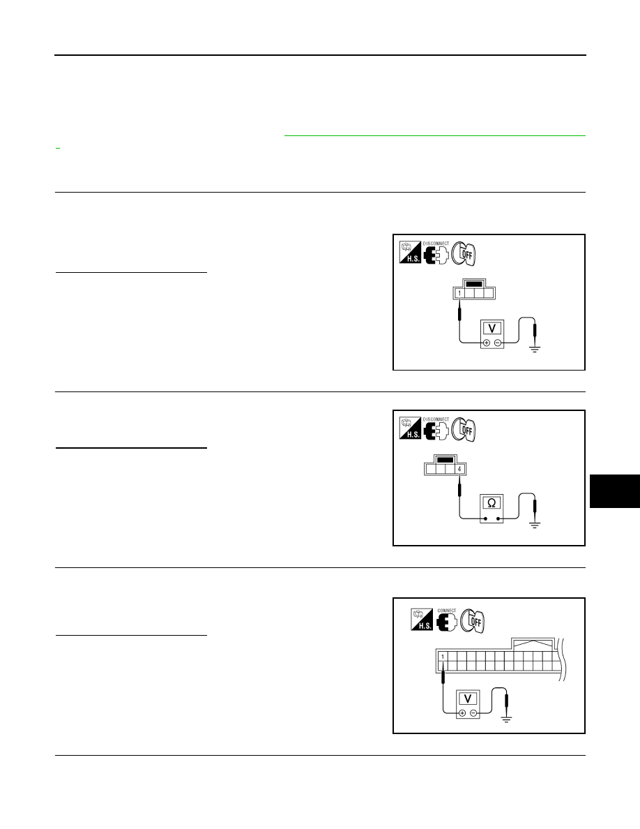
1. Turn ignition switch OFF.
2. Disconnect steering lock solenoid connector.
3. Check voltage between steering lock solenoid harness connector M15 terminal 1 and ground.
Is the inspection result normal?
YES
>> GO TO 2
NO
>> Repair or replace steering lock solenoid power supply
circuit.
2.
CHECK STEERING LOCK SOLENOID GROUND CIRCUIT
Check continuity between steering lock solenoid harness connector M15 terminal 4 and ground.
Is the inspection result normal?
YES
>> GO TO 3
NO
>> Repair or replace the steering lock solenoid ground cir-
cuit.
3.
CHECK INTELLIGENT KEY UNIT OUTPUT SIGNAL
1. Connect steering lock solenoid connector.
2. Check voltage between Intelligent Key unit harness connector M70 terminal 1 and ground.
Is the inspection result normal?
YES
>> GO TO 4
NO
>> GO TO 6
4.
CHECK STEERING LOCK COMMUNICATION SIGNAL
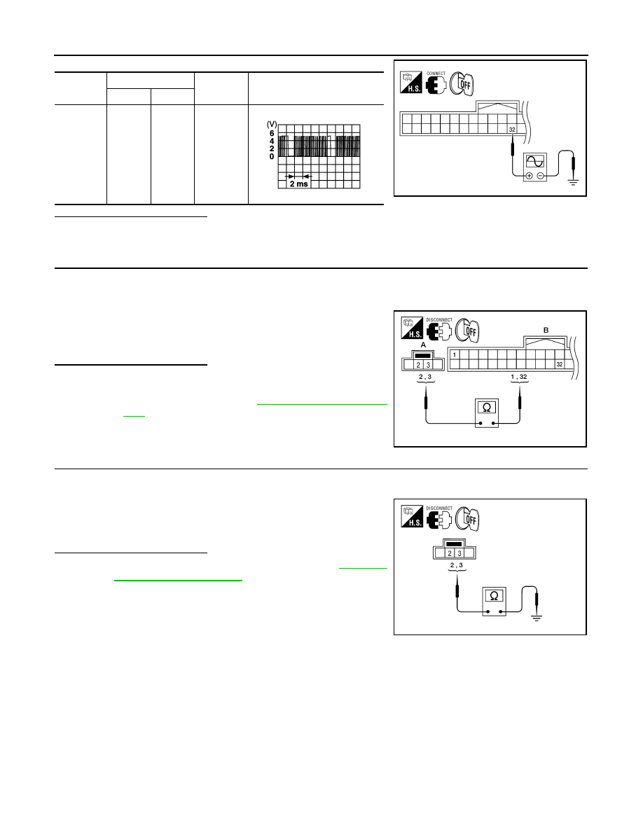
Check signal between Intelligent Key unit connector M70 terminal 32 and ground with oscilloscope.
1 - Ground
: Battery voltage
WIIA1202E
4 - Ground
: Continuity should exist.
WIIA1203E
1 - Ground
: Approx. 5V
WIIA1204E
DLK-100
< COMPONENT DIAGNOSIS >
[WITH INTELLIGENT KEY SYSTEM]
STEERING LOCK UNIT
Is the inspection result normal?
YES
>> GO TO 5
NO
>> GO TO 6
5.
CHECK STEERING LOCK SOLENOID COMMUNICATION CIRCUIT FOR OPEN
1. Disconnect Intelligent Key unit and steering lock solenoid connectors.
2. Check continuity between Intelligent Key unit harness connector (B) M70 terminals 1, 32 and steering lock
solenoid connector (A) M15 terminals 2, 3.
Is the inspection result normal?
YES
>> Replace steering lock solenoid.
• After replacing steering lock solenoid, perform regis-
tration procedure. Refer to
NO
>> Repair or replace harness between steering lock sole-
noid and Intelligent Key unit.
6.
CHECK STEERING LOCK SOLENOID COMMUNICATION CIRCUIT FOR SHORT
1. Disconnect Intelligent Key unit and steering lock solenoid connectors.
2. Check continuity between steering lock solenoid connector M15 terminals 2, 3 and ground.
Is the inspection result normal?
YES
>> Replace Intelligent Key unit. Refer to
.
NO
>> Repair or replace harness between steering lock sole-
noid and Intelligent Key unit.
Connector
Terminals
Condition
Signal (V)
(Reference value)
(+)
(–)
M70
32
Ground
Ignition
switch is
pushed
WIIA1205E
SIIA1911J
1 - 2
: Continuity should exist.
32 - 3
: Continuity should exist.
ALKIA0661ZZ
2 - Ground
: Continuity should not exist.
3 - Ground
: Continuity should not exist.
ALKIA0662ZZ
A/T SHIFT SELECTOR (PARK POSITION SWITCH)
DLK-101
< COMPONENT DIAGNOSIS >
[WITH INTELLIGENT KEY SYSTEM]
C
D
E
F
G
H
I
J
L
M
A
B
DLK
N
O
P
A/T SHIFT SELECTOR (PARK POSITION SWITCH)
Diagnosis Procedure
INFOID:0000000005146971
Regarding Wiring Diagram information, refer to
DLK-178, "Wiring Diagram — INTELLIGENT KEY SYSTEM —
1.
CHECK A/T SHIFT SELECTOR (PARK POSITION SWITCH) INPUT SIGNAL
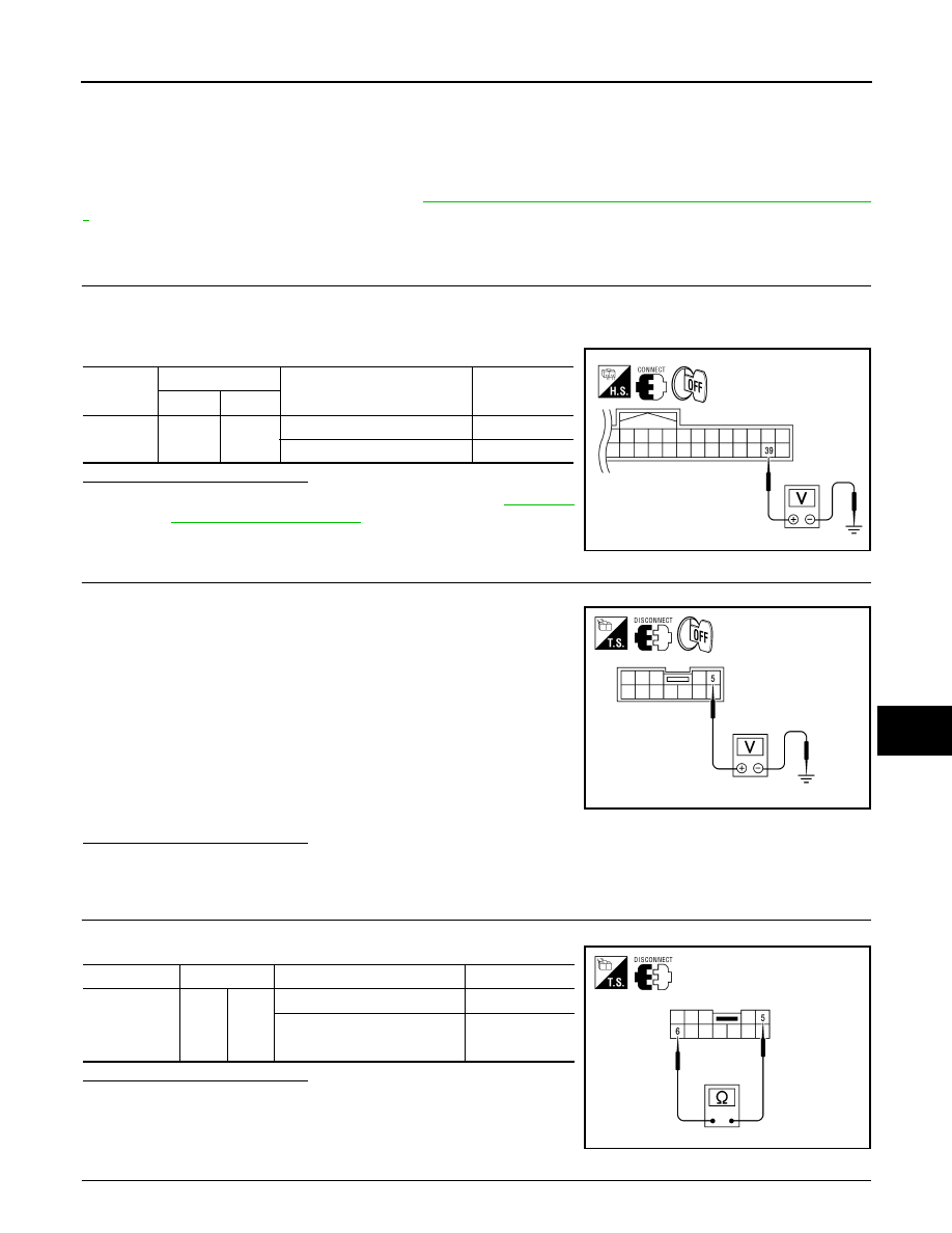
1. Turn ignition switch OFF.
2. While pressing the ignition knob switch, check voltage between Intelligent Key unit harness connector
M70 terminal 39 and ground.
Is the inspection result normal?
YES
>> Replace Intelligent Key unit. Refer to
.
NO
>> GO TO 2
2.
CHECK A/T SHIFT SELECTOR (PARK POSITION SWITCH) POWER SUPPLY CIRCUIT
1. Disconnect A/T shift selector (park position switch) connector.
2. While pressing the ignition knob switch, check voltage between
A/T shift selector (park position switch) harness connector M203
terminal 5 and ground.
Is the inspection result normal?
YES
>> GO TO 3
NO
>> Repair or replace harness or ignition knob switch.
3.
CHECK A/T SHIFT SELECTOR (PARK POSITION SWITCH)
Check continuity between A/T shift selector (park position switch) terminals 5 and 6.
Is the inspection result normal?
YES
>> GO TO 4
NO
>> Replace A/T shift selector (park position switch).
4.
CHECK A/T SHIFT SELECTOR (PARK POSITION SWITCH) CIRCUIT
Connector
Terminals
Condition
Voltage (V)
(Approx.)
(+)
(-)
M70
39
Ground
Selector lever is in "P" position Battery voltage
Other than above
0
WIIA1211E
5 – Ground
: Battery voltage.
ALKIA0663ZZ
Component
Terminals
Condition
Continuity
A/T shift se-
lector (park
position
switch)
5
6
Selector lever is in "P" position
Yes
Other than above
No
ALKIA0664ZZ
DLK-102
< COMPONENT DIAGNOSIS >
[WITH INTELLIGENT KEY SYSTEM]
A/T SHIFT SELECTOR (PARK POSITION SWITCH)
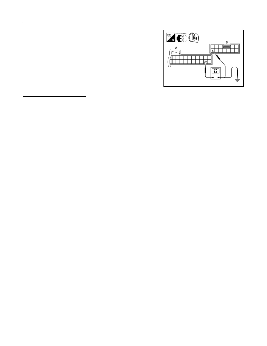
1. Disconnect Intelligent Key unit connector.
2. Check continuity between Intelligent Key unit harness connector
(A) M70 terminal 39 and A/T shift selector (park position switch)
harness connector (B) M203 terminal 6.
3. Check continuity between Intelligent Key unit harness connector
(A) M70 terminals 39 and ground.
Is the inspection result normal?
YES
>> A/T shift selector (park position switch) circuit is OK.
NO
>> Repair or replace harness.
39 – 6
: Continuity should exist.
39 – Ground
: Continuity should not exist.
ALKIA0665ZZ
Нет комментариевНе стесняйтесь поделиться с нами вашим ценным мнением.
Текст