Infiniti QX56 (JA60). Manual — part 235
WARNING CHIME FUNCTION
DLK-111
< COMPONENT DIAGNOSIS >
[WITH INTELLIGENT KEY SYSTEM]
C
D
E
F
G
H
I
J
L
M
A
B
DLK
N
O
P
WARNING CHIME FUNCTION
Description
INFOID:0000000005146984
Performs operation method guide and warning with buzzer.
Component Function Check
INFOID:0000000005146985
1.
CHECK FUNCTION
With CONSULT-III
1. Check the operation with "INSIDE BUZZER" in the Active Test.
2. Touch “TAKE OUT”, “KNOB”or “KEY” on screen.
Is the inspection result normal?
Yes
>> Warning buzzer into combination meter is OK.
No
>> Refer to
DLK-111, "Diagnosis Procedure"
Diagnosis Procedure
INFOID:0000000005146986
1.
CHECK METER BUZZER CIRCUIT
The inoperative warning chime is contained inside the combination meter. Replace combination meter. Refer
to
MWI-100, "Removal and Installation"
>> Inspection End.
DLK-112
< COMPONENT DIAGNOSIS >
[WITH INTELLIGENT KEY SYSTEM]
HAZARD FUNCTION
HAZARD FUNCTION
Description
INFOID:0000000005146987
Perform answer-back for each operation with number of blinks.
Component Function Check
INFOID:0000000005146988
1.
CHECK FUNCTION
Check hazard warning lamp "FLASHER" in ACTIVE TEST.
Is the inspection result normal?
YES
>> Hazard warning lamp circuit is OK.
NO
>> Refer to
DLK-112, "Diagnosis Procedure"
Diagnosis Procedure
INFOID:0000000005146989
1.
CHECK HAZARD SWITCH CIRCUIT
Operate the hazard lights by turning ON the hazard warning switch.
Do the lights operate normally?
YES
>> Replace the BCM. Refer to BCS for replacement and configuration procedure.
NO
>> Repair or replace hazard warning switch circuit. Refer to
KEY SWITCH (INTELLIGENT KEY UNIT INPUT)
DLK-113
< COMPONENT DIAGNOSIS >
[WITH INTELLIGENT KEY SYSTEM]
C
D
E
F
G
H
I
J
L
M
A
B
DLK
N
O
P
KEY SWITCH (INTELLIGENT KEY UNIT INPUT)
Diagnosis Procedure
INFOID:0000000005146990
Regarding Wiring Diagram information, refer to
DLK-178, "Wiring Diagram — INTELLIGENT KEY SYSTEM —
1.
CHECK KEY SWITCH
With CONSULT-III
Check key switch (“KEY SW”) in “DATA MONITOR” mode with CONSULT-III.
Without CONSULT-III
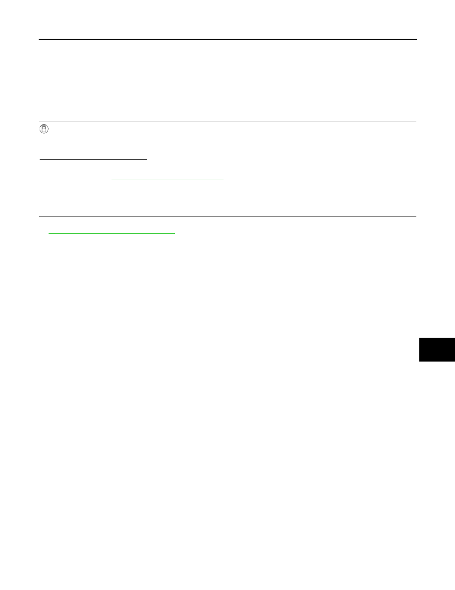
1. Turn ignition switch OFF.
2. Disconnect Intelligent Key unit harness connector.
3. Check voltage between Intelligent Key unit harness connector
M70 terminal 7 and ground.
Is the inspection result normal?
YES
>> Key switch is OK.
NO
>> GO TO 2
2.
CHECK KEY SWITCH POWER SUPPLY CIRCUIT
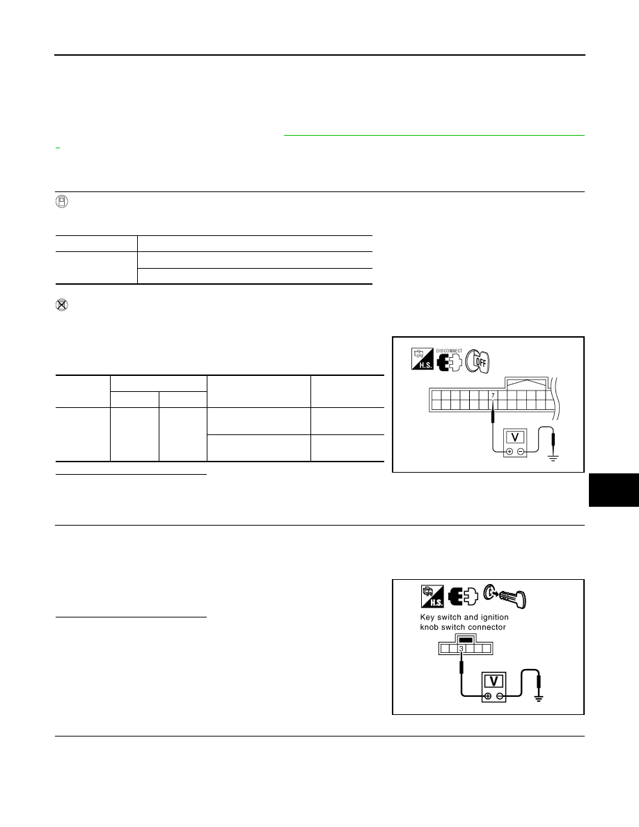
1. Remove mechanical key from ignition switch.
2. Disconnect key switch and ignition knob switch connector.
3. Check voltage between key switch and ignition knob switch harness connector M12 terminal 3 and
ground.
Is the inspection result normal?
YES
>> GO TO 3
NO
>> Repair or replace key switch and ignition knob switch
power supply circuit.
3.
CHECK KEY SWITCH OPERATION
Monitor item
Condition
KEY SW
Insert mechanical key into ignition switch: ON
Remove mechanical key from ignition switch: OFF
Connector
Terminals
Condition
Voltage (V)
(Approx.)
(+)
(–)
M70
7
Ground
Insert mechanical key
into ignition switch
Battery voltage
Remove mechanical
key from ignition switch
0
WIIA1173E
3 - Ground
: Battery voltage
PIIB4254E
DLK-114
< COMPONENT DIAGNOSIS >
[WITH INTELLIGENT KEY SYSTEM]
KEY SWITCH (INTELLIGENT KEY UNIT INPUT)
Check continuity between key switch and ignition knob switch termi-
nals 3 and 4.
Is the inspection result normal?
YES
>> GO TO 4
NO
>> Replace key cylinder assembly (built-in key switch).
4.
CHECK KEY SWITCH CIRCUIT
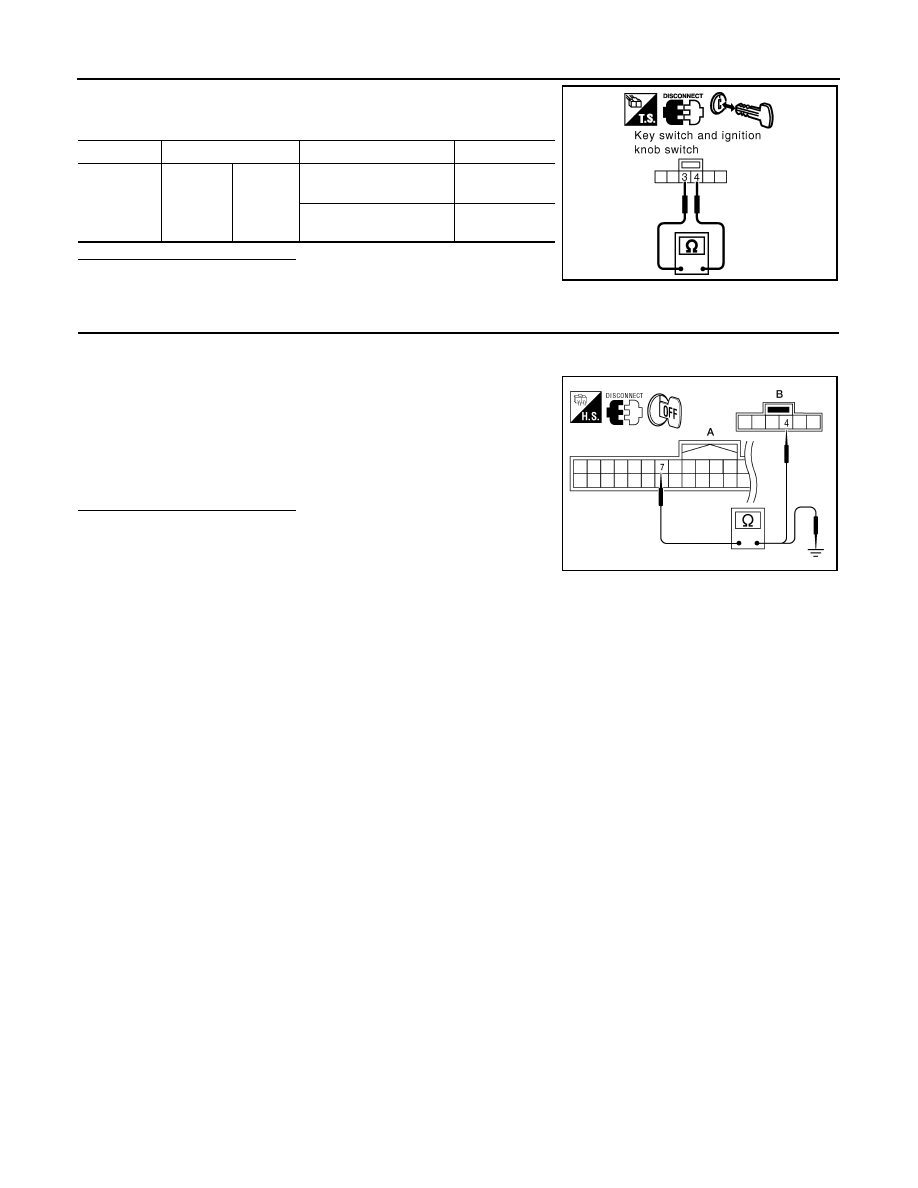
1. Check continuity between Intelligent Key unit harness connector (A) M70 terminal 7 and key switch and
ignition knob switch harness connector (B) M12 terminal 4.
2. Check continuity between Intelligent Key unit harness connector
(A) M70 terminal 7 and ground.
Is the inspection result normal?
YES
>> Check the condition of harness and harness connector.
NO
>> Repair or replace harness between Intelligent Key unit
and key switch and ignition knob switch.
Component
Terminals
Condition
Continuity
Key switch
3
4
Insert mechanical key
into ignition switch.
Yes
Remove mechanical key
from ignition switch.
No
PIIA6140E
7 - 4
: Continuity should exist.
7 - Ground
: Continuity should not exist.
WIIA1174E
Нет комментариевНе стесняйтесь поделиться с нами вашим ценным мнением.
Текст