Infiniti QX56 (JA60). Manual — part 641
PRECAUTIONS
INT-9
< PRECAUTION >
C
D
E
F
G
H
I
K
L
M
A
B
INT
N
O
P
5. When the repair work is completed, return the ignition switch to the
″LOCK″ position before connecting
the battery cables. (At this time, the steering lock mechanism will engage.)
6. Perform a self-diagnosis check of all control units using CONSULT-III.
Service Notice
INFOID:0000000005147346
• When removing or installing various parts, place a cloth or padding on the vehicle body to prevent scratches.
• Handle trim, molding, instruments, grille, etc. carefully during removing or installing. Be careful not to soil or
damage them.
• Apply sealing compound where necessary when installing parts.
• When applying sealing compound, be careful that the sealing compound does not protrude from parts.
• When replacing any metal parts (for example body outer panel, members, etc.), be sure to take rust preven-
tion measures.
INT-10
< PREPARATION >
PREPARATION
PREPARATION
PREPARATION
Special Service Tool
INFOID:0000000005147347
The actual shapes of Kent-Moore tools may differ from those of special service tools illustrated here.
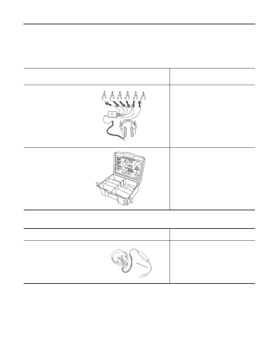
Commercial Service Tool
INFOID:0000000005147348
Tool number
(Kent-Moore No.)
Tool name
Description
—
(J-39570)
Chassis ear
Locating the noise
—
(J-43980)
NISSAN Squeak and Rattle kit
Repairing the cause of noise
SBT839
SBT840
Tool name
(Kent-Moore No.)
Description
Engine ear
(J-39565)
Locating the noise
SIIA0995E
DOOR FINISHER
INT-11
< ON-VEHICLE REPAIR >
C
D
E
F
G
H
I
K
L
M
A
B
INT
N
O
P
ON-VEHICLE REPAIR
DOOR FINISHER
Removal and Installation
INFOID:0000000005147349
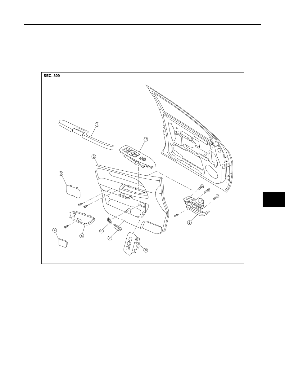
FRONT DOOR
Removal
1. Remove the power window switch assembly.
• Disconnect the harness connectors.
2. Remove the cap from the inside door handle escutcheon and remove screw.
3. Remove the pull handle cover.
• Remove the screws behind pull handle cover.
4. Remove the seat memory switch.
• Disconnect the harness connector.
5. Remove the step lamp.
1.
Armrest
2.
Front door finisher (LH shown)
3.
Pull handle cover
4.
Cap
5.
Inside door handle escutcheon
6.
Door lock knob
7.
Step lamp
8.
Seat memory switch
9.
Inside door handle assembly
10. Power window switch assembly
AWJIA0450ZZ
INT-12
< ON-VEHICLE REPAIR >
DOOR FINISHER
• Disconnect the harness connector.
6. Remove the door finisher and disconnect the lock cable and handle cable from the inside door handle
assembly. Refer to
INT-11, "Removal and Installation"
7. Remove the inside door handle assembly.
8. Remove door lock knob.
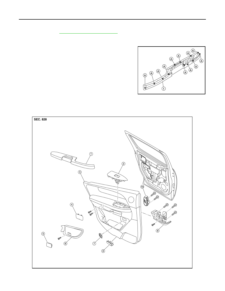
9. Remove the armrest screws (A), then remove the armrest (1).
Installation
Installation is in the reverse order of removal.
REAR DOOR
AWJIA0452ZZ
AWJIA0451ZZ
Нет комментариевНе стесняйтесь поделиться с нами вашим ценным мнением.
Текст