Infiniti QX56 (JA60). Manual — part 640
SQUEAK AND RATTLE TROUBLE DIAGNOSES
INT-5
< SYMPTOM DIAGNOSIS >
C
D
E
F
G
H
I
K
L
M
A
B
INT
N
O
P
2. Trunk lid striker out of adjustment
3. The trunk lid torsion bars knocking together
4. A loose license plate or bracket
Most of these incidents can be repaired by adjusting, securing or insulating the item(s) or component(s) caus-
ing the noise.
SUNROOF/HEADLINING
Noises in the sunroof/headlining area can often be traced to one of the following:
1. Sunroof lid, rail, linkage or seals making a rattle or light knocking noise
2. Sun visor shaft shaking in the holder
3. Front or rear windshield touching headliner and squeaking
Again, pressing on the components to stop the noise while duplicating the conditions can isolate most of these
incidents. Repairs usually consist of insulating with felt cloth tape.
OVERHEAD CONSOLE (FRONT AND REAR)
Overhead console noises are often caused by the console panel clips not being engaged correctly. Most of
these incidents are repaired by pushing up on the console at the clip locations until the clips engage.
In addition look for:
1. Loose harness or harness connectors.
2. Front console map/reading lamp lens loose.
3. Loose screws at console attachment points.
SEATS
When isolating seat noise it's important to note the position the seat is in and the load placed on the seat when
the noise is present. These conditions should be duplicated when verifying and isolating the cause of the
noise.
Cause of seat noise include:
1. Headrest rods and holder
2. A squeak between the seat pad cushion and frame
3. The rear seatback lock and bracket
These noises can be isolated by moving or pressing on the suspected components while duplicating the con-
ditions under which the noise occurs. Most of these incidents can be repaired by repositioning the component
or applying urethane tape to the contact area.
UNDERHOOD
Some interior noise may be caused by components under the hood or on the engine wall. The noise is then
transmitted into the passenger compartment.
Causes of transmitted underhood noise include:
1. Any component installed to the engine wall
2. Components that pass through the engine wall
3. Engine wall mounts and connectors
4. Loose radiator installation pins
5. Hood bumpers out of adjustment
6. Hood striker out of adjustment
These noises can be difficult to isolate since they cannot be reached from the interior of the vehicle. The best
method is to secure, move or insulate one component at a time and test drive the vehicle. Also, engine RPM
or load can be changed to isolate the noise. Repairs can usually be made by moving, adjusting, securing, or
insulating the component causing the noise.
INT-6
< SYMPTOM DIAGNOSIS >
SQUEAK AND RATTLE TROUBLE DIAGNOSES
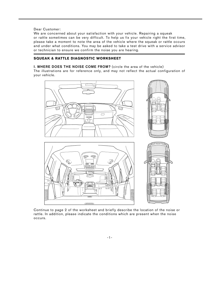
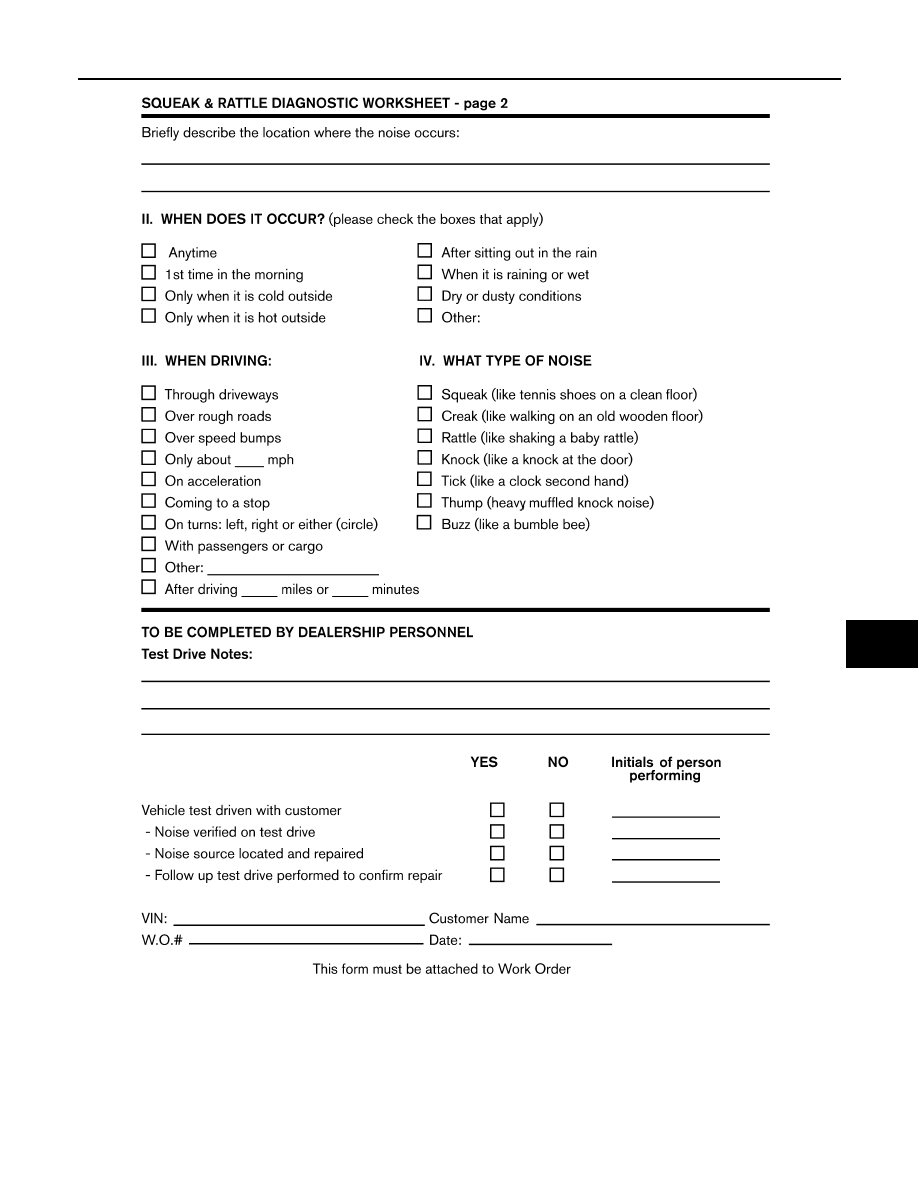
Diagnostic Worksheet
INFOID:0000000005147344
LAIA0072E
SQUEAK AND RATTLE TROUBLE DIAGNOSES
INT-7
< SYMPTOM DIAGNOSIS >
C
D
E
F
G
H
I
K
L
M
A
B
INT
N
O
P
LAIA0071E
INT-8
< PRECAUTION >
PRECAUTIONS
PRECAUTION
PRECAUTIONS
Precaution for Supplemental Restraint System (SRS) "AIR BAG" and "SEAT BELT
PRE-TENSIONER"
INFOID:0000000005376802
The Supplemental Restraint System such as “AIR BAG” and “SEAT BELT PRE-TENSIONER”, used along
with a front seat belt, helps to reduce the risk or severity of injury to the driver and front passenger for certain
types of collision. This system includes seat belt switch inputs and dual stage front air bag modules. The SRS
system uses the seat belt switches to determine the front air bag deployment, and may only deploy one front
air bag, depending on the severity of a collision and whether the front occupants are belted or unbelted.
Information necessary to service the system safely is included in the SR and SB section of this Service Man-
ual.
WARNING:
• To avoid rendering the SRS inoperative, which could increase the risk of personal injury or death in
the event of a collision which would result in air bag inflation, all maintenance must be performed by
an authorized NISSAN/INFINITI dealer.
• Improper maintenance, including incorrect removal and installation of the SRS, can lead to personal
injury caused by unintentional activation of the system. For removal of Spiral Cable and Air Bag
Module, see the SR section.
• Do not use electrical test equipment on any circuit related to the SRS unless instructed to in this
Service Manual. SRS wiring harnesses can be identified by yellow and/or orange harnesses or har-
ness connectors.
PRECAUTIONS WHEN USING POWER TOOLS (AIR OR ELECTRIC) AND HAMMERS
WARNING:
• When working near the Airbag Diagnosis Sensor Unit or other Airbag System sensors with the Igni-
tion ON or engine running, DO NOT use air or electric power tools or strike near the sensor(s) with a
hammer. Heavy vibration could activate the sensor(s) and deploy the air bag(s), possibly causing
serious injury.
• When using air or electric power tools or hammers, always switch the Ignition OFF, disconnect the
battery, and wait at least 3 minutes before performing any service.
Precaution Necessary for Steering Wheel Rotation After Battery Disconnect
INFOID:0000000005376803
NOTE:
• This Procedure is applied only to models with Intelligent Key system and NATS (NISSAN ANTI-THEFT SYS-
TEM).
• Remove and install all control units after disconnecting both battery cables with the ignition knob in the
″LOCK″ position.
• Always use CONSULT-III to perform self-diagnosis as a part of each function inspection after finishing work.
If DTC is detected, perform trouble diagnosis according to self-diagnostic results.
For models equipped with the Intelligent Key system and NATS, an electrically controlled steering lock mech-
anism is adopted on the key cylinder.
For this reason, if the battery is disconnected or if the battery is discharged, the steering wheel will lock and
steering wheel rotation will become impossible.
If steering wheel rotation is required when battery power is interrupted, follow the procedure below before
starting the repair operation.
OPERATION PROCEDURE
1. Connect both battery cables.
NOTE:
Supply power using jumper cables if battery is discharged.
2. Use the Intelligent Key or mechanical key to turn the ignition switch to the
″ACC″ position. At this time, the
steering lock will be released.
3. Disconnect both battery cables. The steering lock will remain released and the steering wheel can be
rotated.
4. Perform the necessary repair operation.
Нет комментариевНе стесняйтесь поделиться с нами вашим ценным мнением.
Текст