Infiniti QX56 (JA60). Manual — part 30
DOOR MIRROR MOTOR
ADP-111
< COMPONENT DIAGNOSIS >
C
D
E
F
G
H
I
K
L
M
A
B
ADP
N
O
P
Door mirror RH
Is the inspection result normal?
YES
>> GO TO 4
NO
>> Replace automatic drive positioner control unit. Refer to
ADP-175, "Removal and Installation"
.
4.
CHECK DOOR MIRROR MOTOR
Check door mirror motor.
ADP-111, "Component Inspection"
Is the inspection result normal?
YES
>> Refer to
GI-38, "Intermittent Incident"
.
NO
>> Replace door mirror actuator. Refer to
.
Component Inspection
INFOID:0000000005147571
1.
CHECK DOOR MIRROR MOTOR-I
Check that door mirror motor does not trap foreign objects and does not have any damage.
MIR-17, "Door Mirror Assembly"
Is the inspection result normal?
YES
>> GO TO 2
NO
>> Replace door mirror actuator. Refer to
.
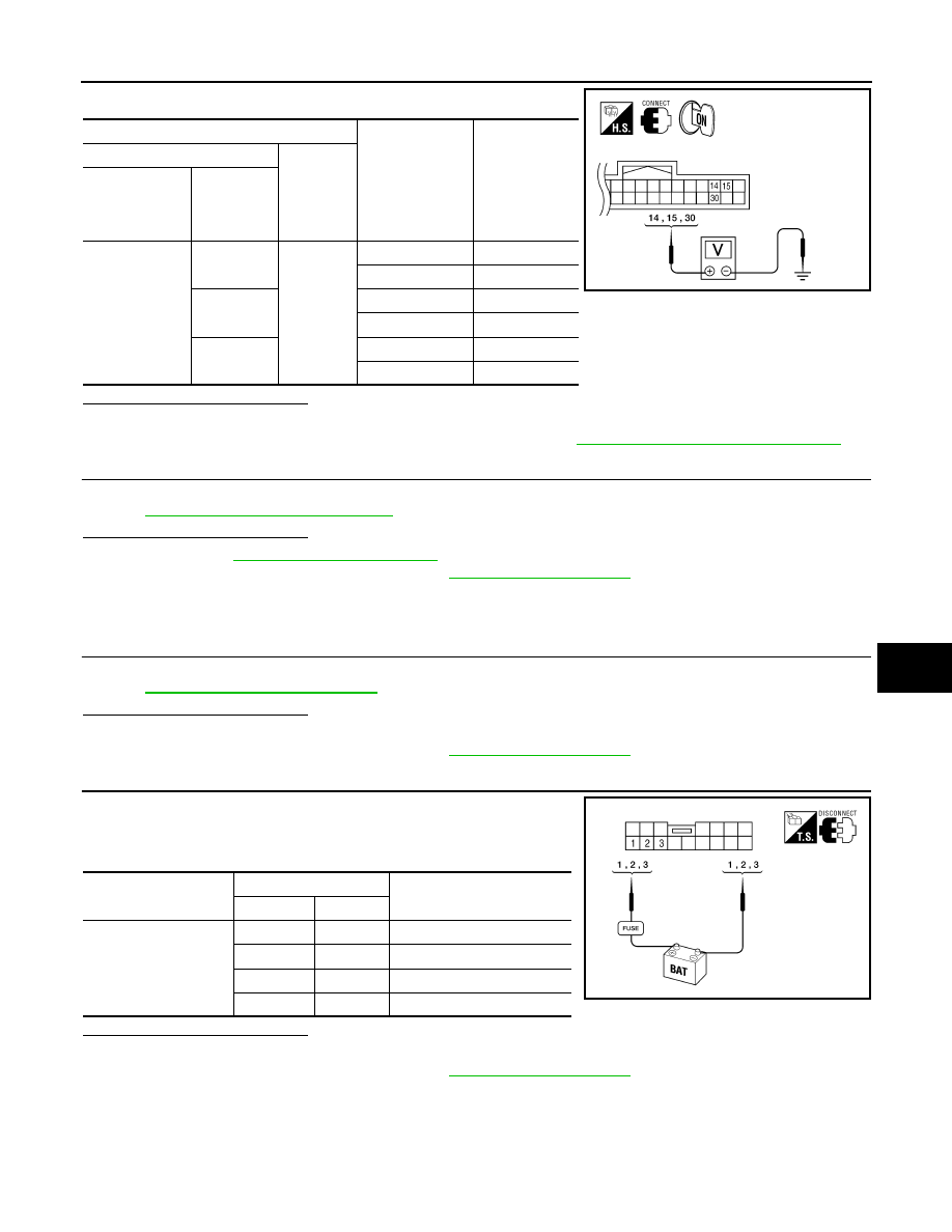
2.
CHECK DOOR MIRROR MOTOR-II
1. Turn ignition switch OFF.
2. Disconnect door mirror.
3. Apply 12V to each power supply terminal of door mirror motor.
Is the inspection result normal?
YES
>> Inspection End.
NO
>> Replace door mirror actuator. Refer to
.
Terminals
Mirror switch con-
dition
Voltage (V)
(Approx.)
(+)
(-)
Automatic drive
positioner con-
trol unit connec-
tor
Terminal
M33
14
Ground
UP
Battery voltage
Other than above
0
15
LEFT
Battery voltage
Other than above
0
30
DOWN / RIGHT
Battery voltage
Other than above
0
ALJIA0198ZZ
Door mirror connector
Terminal
Operational direction
(+)
(–)
D4 (LH)
D107 (RH)
3
2
RIGHT
2
3
LEFT
1
3
UP
3
1
DOWN
ALJIA0199ZZ
ADP-112
< COMPONENT DIAGNOSIS >
SEAT MEMORY INDICATOR LAMP
SEAT MEMORY INDICATOR LAMP
Description
INFOID:0000000005147572
• The seat memory switch is installed on the driver side door trim. The operation signal is inputted to the auto-
matic drive positioner control unit when the memory switch is operated.
• The status of automatic drive positioner system can be checked according to the illuminating/flashing status.
Component Function Check
INFOID:0000000005147573
1.
CHECK FUNCTION
1. Select “MEMORY SW INDCTR” in “Active test” mode with CONSULT-III.
2. Check the memory indicator operation.
Is the operation of relevant parts normal?
YES
>> Inspection End.
NO
>> Perform diagnosis procedure. Refer to
ADP-112, "Diagnosis Procedure"
.
Diagnosis Procedure
INFOID:0000000005147574
Regarding Wiring Diagram information, refer to
1.
CHECK SEAT MEMORY INDICATOR CIRCUIT
1. Turn ignition switch OFF.
2. Disconnect automatic drive positioner control unit and seat
memory switch.
3. Check continuity between automatic drive positioner control unit
harness connector and seat memory switch harness connector.
4. Check continuity between automatic drive positioner control unit harness connector and ground.
Is the inspection result normal?
YES
>> GO TO 2
NO
>> Repair or replace harness.
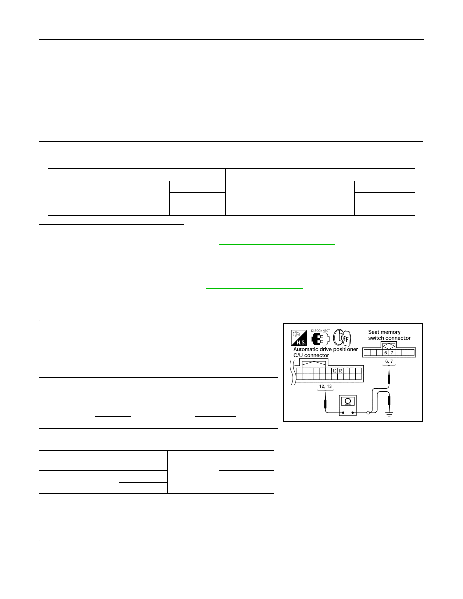
2.
CHECK MEMORY INDICATOR POWER SUPPLY
Test item
Description
MEMORY SW INDCTR
OFF
Memory switch indicator
OFF
ON-1
Indicator 1: ON
ON-2
Indicator 2: ON
Automatic drive
positioner control
unit connector
Terminal
Seat memory switch
connector
Terminal
Continuity
M33
12
D5
6
Yes
13
7
Automatic drive position-
er connector
Terminal
Ground
Continuity
M33
12
No
13
LIIA1022E
SEAT MEMORY INDICATOR LAMP
ADP-113
< COMPONENT DIAGNOSIS >
C
D
E
F
G
H
I
K
L
M
A
B
ADP
N
O
P
Check voltage between seat memory switch harness connector and
ground.
Is the inspection result normal?
YES
>> GO TO 3
NO
>> Check the following.
• Fuse
• Harness for open or short between memory indicator and fuse.
3.
CHECK MEMORY INDICATOR
ADP-113, "Component Inspection"
Is the inspection result normal?
YES
>> GO TO 4
NO
>> Replace seat memory switch. Refer to
ADP-176, "Removal and Installation"
.
4.
CHECK INTERMITTENT INCIDENT
GI-38, "Intermittent Incident"
.
Is the inspection result normal?
YES
>> Replace automatic drive positioner control unit. Refer to
ADP-175, "Removal and Installation"
.
NO
>> Repair or replace the malfunctioning part.
Component Inspection
INFOID:0000000005147575
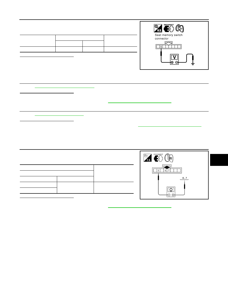
1.
CHECK SEAT MEMORY INDICATOR
1. Disconnect seat memory switch.
2. Check continuity between seat memory switch terminals.
Is the inspection result normal?
YES
>> Inspection End.
NO
>> Replace seat memory switch. Refer to
ADP-176, "Removal and Installation"
.
Seat memory switch
connector
Terminals
Voltage (V)
(Approx.)
(+)
(–)
D5
5
Ground
Battery voltage
PIIA4595E
Terminal
Continuity
Seat memory switch
(+)
(-)
6
5
Yes
7
ALJIA0200ZZ

ADP-114
< ECU DIAGNOSIS >
DRIVER SEAT CONTROL UNIT
ECU DIAGNOSIS
DRIVER SEAT CONTROL UNIT
Reference Value
INFOID:0000000005147576
VALUES ON THE DIAGNOSIS TOOL
CONSULT-III MONITOR ITEM
Monitor Item
Condition
Value/Status
SET SW
Set switch
Push
ON
Release
OFF
MEMORY SW1
Memory switch 1
Push
ON
Release
OFF
MEMORY SW2
Memory switch 2
Push
ON
Release
OFF
SLIDE SW–FR
Sliding switch (front)
Operate
ON
Release
OFF
SLIDE SW–RR
Sliding switch (rear)
Operate
ON
Release
OFF
RECLN SW–FR
Reclining switch (front)
Operate
ON
Release
OFF
RECLN SW–RR
Reclining switch (rear)
Operate
ON
Release
OFF
LIFT FR SW–UP
Lifting switch front (up)
Operate
ON
Release
OFF
LIFT FR SW–DN
Lifting switch front (down)
Operate
ON
Release
OFF
LIFT RR SW–UP
Lifting switch rear (up)
Operate
ON
Release
OFF
LIFT RR SW–DN
Lifting switch rear (down)
Operate
ON
Release
OFF
MIR CON SW–UP
Mirror switch
Up
ON
Other than above
OFF
MIR CON SW–DN
Mirror switch
Down
ON
Other than above
OFF
MIR CON SW–RH
Mirror switch
Right
ON
Other than above
OFF
MIR CON SW–LH
Mirror switch
Left
ON
Other than above
OFF
MIR CHNG SW–R
Changeover switch
Right
ON
Other than above
OFF
MIR CHNG SW–L
Changeover switch
Left
ON
Other than above
OFF
PEDAL SW-FR
Pedal adjusting switch
Forward
ON
Other than above
OFF
PEDAL SW-RR
Pedal adjusting switch
Backward
ON
Other than above
OFF
Нет комментариевНе стесняйтесь поделиться с нами вашим ценным мнением.
Текст