Infiniti QX56 (JA60). Manual — part 29
PEDAL ADJUSTING MOTOR
ADP-107
< COMPONENT DIAGNOSIS >
C
D
E
F
G
H
I
K
L
M
A
B
ADP
N
O
P
PEDAL ADJUSTING MOTOR
Description
INFOID:0000000005147565
• The pedal adjusting motor is installed to the pedal assembly.
• The pedal adjusting motor is activated with the automatic drive positioner control unit.
• The pedal assembly is adjusted forward/backward by changing the rotation direction of pedal adjusting
motor.
Component Function Check
INFOID:0000000005147566
1.
CHECK FUNCTION
1. Select “ADJ PEDAL MOTOR” in “Active test” mode with CONSULT-III.
2. Check the pedal adjusting motor operation.
Is the operation of relevant parts normal?
YES
>> Inspection End.
NO
>> Perform diagnosis procedure. Refer to
ADP-107, "Diagnosis Procedure"
Diagnosis Procedure
INFOID:0000000005147567
Regarding Wiring Diagram information, refer to
1.
CHECK PEDAL ADJUSTING MOTOR POWER SUPPLY
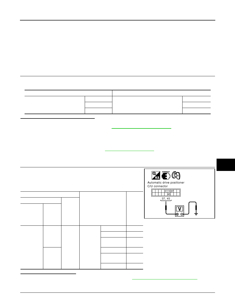
1. Turn the ignition switch OFF.
2. Perform “Active test” (“ADJ PEDAL MOTOR”) with CONSULT-lll.
3. Check voltage between automatic drive positioner control unit
harness connector and ground.
Is the inspection result normal?
YES
>> Replace pedal adjusting motor assembly. Refer to
ADP-178, "Removal and Installation"
.
NO
>> GO TO 2
2.
CHECK PEDAL ADJUSTING MOTOR CIRCUIT
Test item
Description
ADJ PEDAL MOTOR
OFF
Pedal adjusting motor
Stop
FR
Forward
RR
Backward
Terminal
Test Item
Voltage
(V)
(Approx.)
(+)
(-)
Automatic
drive posi-
tioner con-
trol unit
connector
Terminal
M34
37
Ground
ADJ PED-
AL MOTOR
OFF
0
RR (backward)
0
FR (forward)
Battery
voltage
45
OFF
0
RR (backward)
Battery
voltage
FR (forward)
0
PIIA4806E
ADP-108
< COMPONENT DIAGNOSIS >
PEDAL ADJUSTING MOTOR
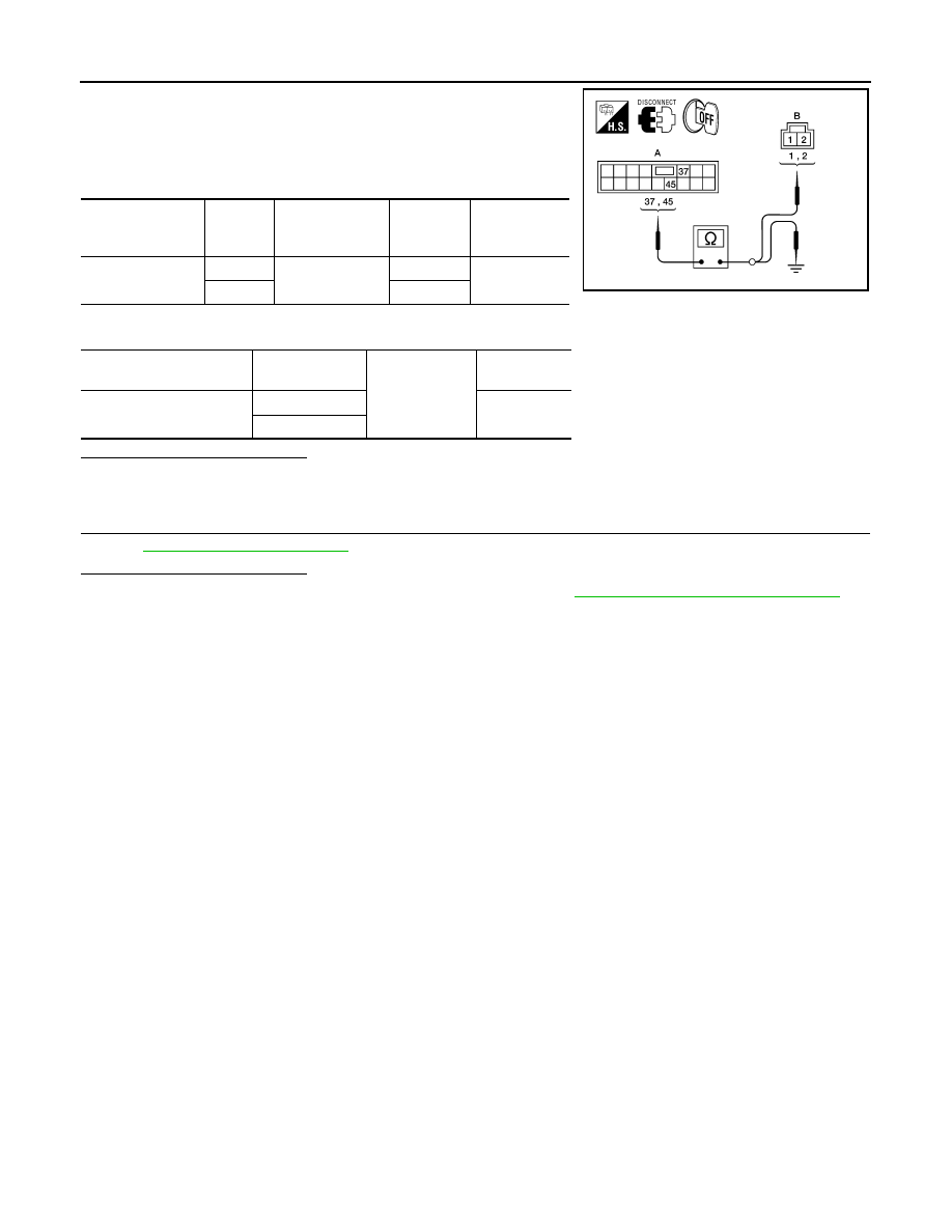
1. Disconnect automatic drive positioner control unit and pedal
adjusting motor assembly.
2. Check continuity between automatic drive positioner control unit
harness connector and pedal adjusting motor assembly harness
connector.
3. Check continuity between automatic drive positioner control unit harness connector and ground.
Is the inspection result normal?
YES
>> GO TO 3
NO
>> Repair or replace harness.
3.
CHECK INTERMITTENT INCIDENT
GI-38, "Intermittent Incident"
Is the inspection result normal?
YES
>> Replace automatic drive positioner control unit. Refer to
ADP-175, "Removal and Installation"
NO
>> Repair or replace the malfunctioning part.
Automatic drive
positioner control
unit connector
Terminal
Pedal adjusting
motor assembly
connector
Terminal
Continuity
M34 (A)
37
E109 (B)
1
Yes
45
2
Automatic drive positioner
control unit connector
Terminal
Ground
Continuity
M34 (A)
37
No
45
ALJIA0195ZZ
DOOR MIRROR MOTOR
ADP-109
< COMPONENT DIAGNOSIS >
C
D
E
F
G
H
I
K
L
M
A
B
ADP
N
O
P
DOOR MIRROR MOTOR
Description
INFOID:0000000005147568
It makes mirror face operate from side to side and up and down with the electric power that automatic drive
positioner control unit supplies.
Component Function Check
INFOID:0000000005147569
1.
CHECK DOOR MIRROR MOTOR FUNCTION
Check the operation with “MIRROR MOTOR RH” and “MIRROR MOTOR LH” in “ACTIVE TEST” mode with
CONSULT-III
ADP-28, "CONSULT-III Function"
.
Is the inspection result normal?
YES
>> Door mirror motor function is OK.
NO
>> Refer to
ADP-109, "Diagnosis Procedure"
Diagnosis Procedure
INFOID:0000000005147570
Regarding Wiring Diagram information, refer to
1.
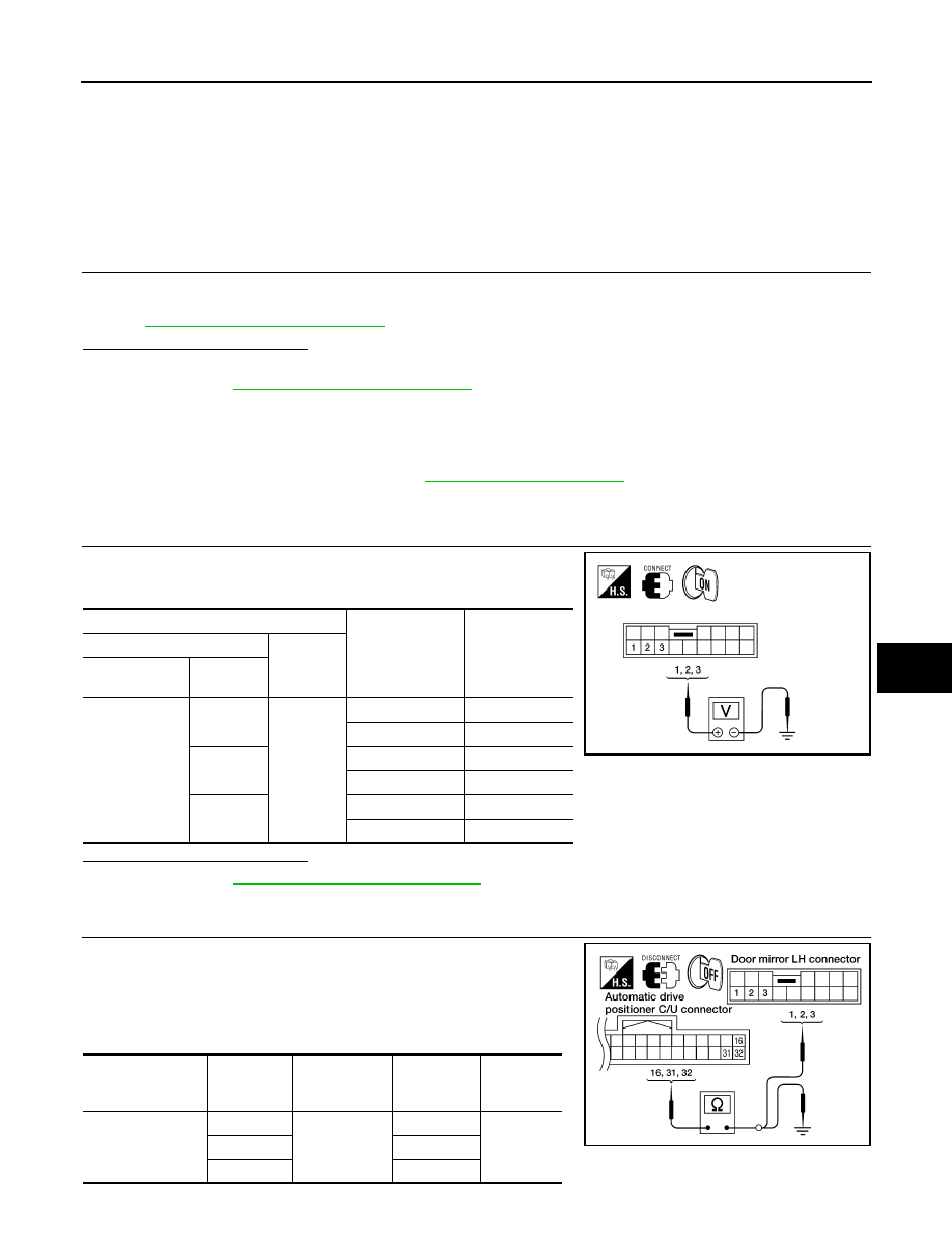
CHECK DOOR MIRROR MOTOR INPUT SIGNAL
1. Turn ignition switch ON.
2. Check voltage between door mirror connector and ground.
Is the inspection result normal?
YES
>> Refer to
ADP-111, "Component Inspection"
NO
>> GO TO 2
2.
CHECK HARNESS CONTINUITY
1. Turn ignition switch OFF.
2. Disconnect automatic drive positioner control unit and door mir-
ror.
3. Check continuity between automatic drive positioner control unit
connector and door mirror connector.
Door mirror LH
Terminals
Door mirror re-
mote control
switch condition
Voltage (V)
(Approx.)
(+)
(–)
Door mirror
connector
Terminal
D4 (LH)
D107 (RH)
1
Ground
UP
Battery voltage
Other than above
0
2
LEFT
Battery voltage
Other than above
0
3
DOWN / RIGHT
Battery voltage
Other than above
0
ALJIA0196ZZ
Automatic drive
positioner control
unit connector
Terminal
Door mirror LH
connector
Terminal
Continuity
M33
16
D4
3
Yes
31
1
32
2
LIIA1880E
ADP-110
< COMPONENT DIAGNOSIS >
DOOR MIRROR MOTOR
Door mirror RH
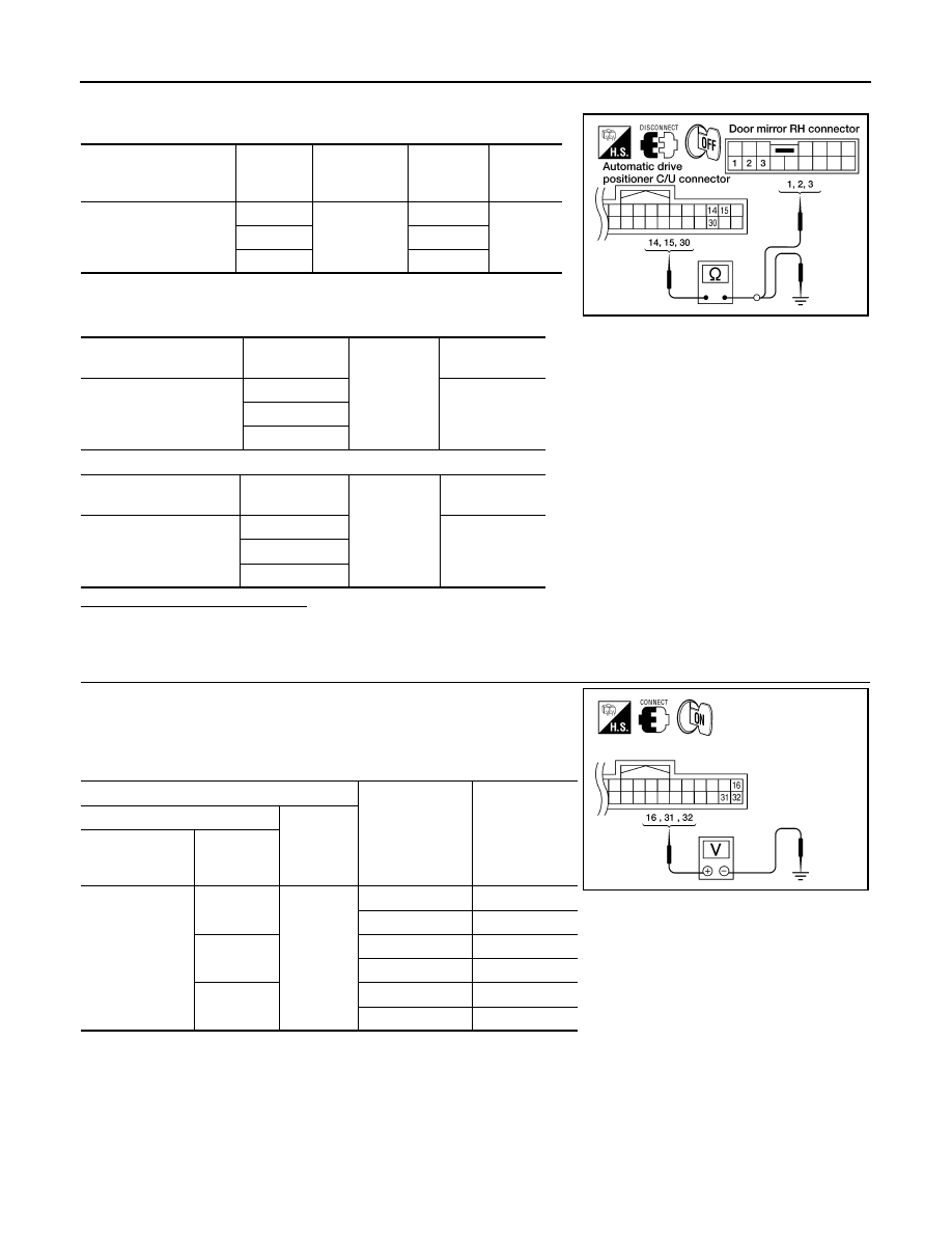
4. Check continuity between automatic drive positioner control unit
connector and ground.
Door mirror LH
Door mirror RH
Is the inspection result normal?
YES
>> GO TO 3
NO
>> Repair or replace harness.
3.
CHECK AUTOMATIC DRIVE POSITIONER CONTROL UNIT OUTPUT SIGNAL
1. Connect automatic drive positioner control unit.
2. Turn ignition switch ON.
3. Check voltage between automatic drive positioner control unit
connector and ground.
Door mirror LH
Automatic drive posi-
tioner control unit con-
nector
Terminal
Door mirror
RH connector
Terminal
Continuity
M33
14
D107
1
Yes
15
2
30
3
Automatic drive position-
er control unit connector
Terminal
Ground
Continuity
M33
16
No
31
32
Automatic drive position-
er control unit connector
Terminal
Ground
Continuity
M33
14
No
15
30
LIIA1888E
Terminals
Mirror switch
condition
Voltage (V)
(Approx.)
(+)
(-)
Automatic drive
positioner control
unit connector
Terminal
M33
16
Ground
DOWN / RIGHT
Battery voltage
Other than above
0
31
UP
Battery voltage
Other than above
0
32
LEFT
Battery voltage
Other than above
0
ALJIA0197ZZ
Нет комментариевНе стесняйтесь поделиться с нами вашим ценным мнением.
Текст