Infiniti QX56 (JA60). Manual — part 28
LIFTING MOTOR (REAR)
ADP-103
< COMPONENT DIAGNOSIS >
C
D
E
F
G
H
I
K
L
M
A
B
ADP
N
O
P
LIFTING MOTOR (REAR)
Description
INFOID:0000000005147559
• The lifting motor (rear) is installed to the power seat frame assembly.
• The lifting motor (rear) is activated with the driver seat control unit.
• The seat lifter (rear) is moved upward/downward by changing the rotation direction of lifting motor (rear).
Component Function Check
INFOID:0000000005147560
1.
CHECK FUNCTION
1. Select “SEAT LIFTER RR” in “Active test” mode with CONSULT-III.
2. Check the lifting motor (rear) operation.
Is the operation of relevant parts normal?
YES
>> Inspection End.
NO
>> Perform diagnosis procedure. Refer to
ADP-103, "Diagnosis Procedure"
Diagnosis Procedure
INFOID:0000000005147561
Regarding Wiring Diagram information, refer to
1.
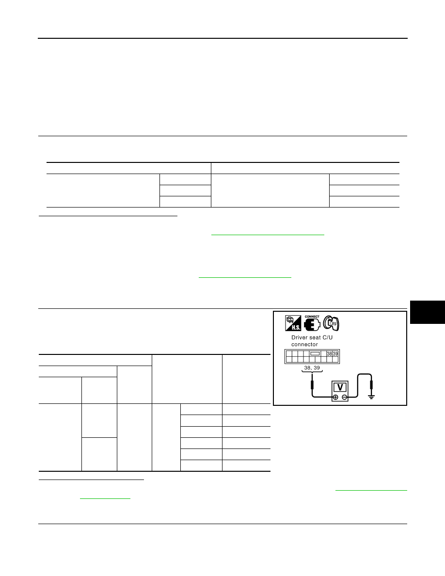
CHECK LIFTING MOTOR (REAR) POWER SUPPLY
1. Turn the ignition switch OFF.
2. Perform “Active test” (“SEAT LIFTER RR”) with CONSULT-lll
3. Check voltage between driver seat control unit harness connec-
tor and ground.
Is the inspection result normal?
YES
>> Replace lifting motor (rear). (Built in power seat frame assembly). Refer to
.
NO
>> GO TO 2
2.
CHECK LIFTING MOTOR (REAR) CIRCUIT
Test Item
Description
SEAT LIFTER RR
OFF
Seat lifting (rear)
Stop
UP
Upward
DWN
Downward
Terminal
Test Item
Voltage (V)
(Approx.)
(+)
(-)
Driver seat
control unit
connector
Terminal
B203
38
Ground
SEAT
LIFTER
RR
OFF
0
UP
Battery voltage
DWN (down)
0
39
OFF
0
UP
0
DWN (down) Battery voltage
PIIA4804E
ADP-104
< COMPONENT DIAGNOSIS >
LIFTING MOTOR (REAR)
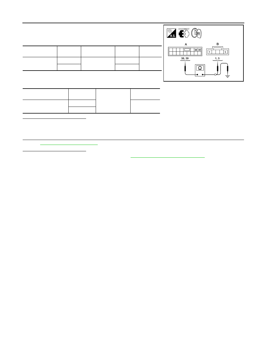
1. Disconnect driver seat control unit and lifting motor (rear).
2. Check continuity between driver seat control unit harness con-
nector and lifting motor (rear) harness connector.
3. Check continuity between driver seat control unit harness con-
nector and ground.
Is the inspection result normal?
YES
>> GO TO 3
NO
>> Repair or replace harness.
3.
CHECK INTERMITTENT INCIDENT
GI-38, "Intermittent Incident"
Is the inspection result normal?
YES
>> Replace driver seat control unit. Refer to
ADP-174, "Removal and Installation"
NO
>> Repair or replace the malfunctioning part.
Driver seat control
unit connector
Terminal
Lifting motor (rear)
connector
Terminal
Continuity
B203 (A)
38
B207 (B)
5
Yes
39
1
Driver seat control unit
connector
Terminal
Ground
Continuity
B203 (A)
38
No
39
ALJIA0324ZZ
TILT MOTOR
ADP-105
< COMPONENT DIAGNOSIS >
C
D
E
F
G
H
I
K
L
M
A
B
ADP
N
O
P
TILT MOTOR
Description
INFOID:0000000005147562
• The tilt motor is installed to the steering column assembly.
• The tilt motor is activated with the automatic drive positioner control unit.
• The steering column is tilted upward/downward by changing the rotation direction of tilt motor.
Component Function Check
INFOID:0000000005147563
1.
CHECK FUNCTION
1. Select “TILT MOTOR” in “Active test” mode with CONSULT-III.
2. Check the tilt motor operation.
Is the operation of relevant parts normal?
YES
>> Inspection End.
NO
>> Perform diagnosis procedure. Refer to
ADP-105, "Diagnosis Procedure"
Diagnosis Procedure
INFOID:0000000005147564
Regarding Wiring Diagram information, refer to
1.
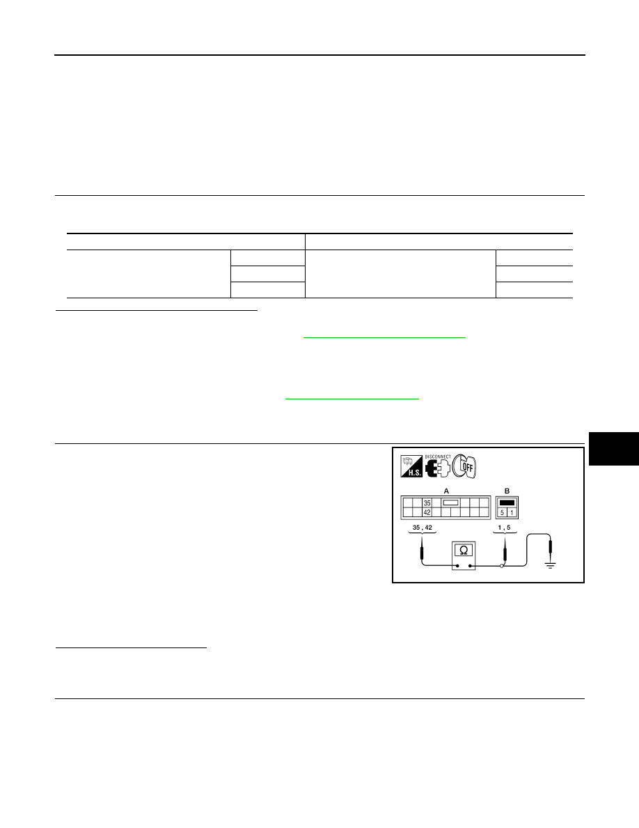
CHECK TILT MOTOR HARNESS CONTINUITY
1. Turn ignition switch OFF.
2. Disconnect automatic drive positioner control unit and tilt motor
assembly.
3. Check continuity between automatic drive positioner control unit
connector M34 (A) terminals 35, 42 and tilt motor assembly con-
nector M86 (B) terminals 1, 5.
4. Check continuity between automatic drive positioner control unit
connector M34 (A) terminals 35, 42 and ground.
Is the inspection result normal?
YES
>> GO TO 2
NO
>> Repair or replace harness.
2.
CHECK AUTOMATIC DRIVE POSITIONER CONTROL UNIT OUTPUT SIGNAL
Test item
Description
TILT MOTOR
OFF
Steering tilt
Stop
UP
Upward
DWN
Downward
35 - 1
: Continuity should exist.
42 - 5
: Continuity should exist.
35 - Ground
: Continuity should not exist.
42 - Ground
: Continuity should not exist.
ALJIA0293ZZ

ADP-106
< COMPONENT DIAGNOSIS >
TILT MOTOR
1. Connect the automatic drive positioner control unit and tilt motor
assembly.
2. Check voltage between automatic drive positioner control unit
connector and ground.
Is the inspection result normal?
YES
>> Replace tilt motor assembly. Refer to
ST-19, "Removal and Installation"
.
NO
>> GO TO 3
3.
CHECK INTERMITTENT INCIDENT
GI-38, "Intermittent Incident"
Is the inspection result normal?
YES
>> Replace automatic drive positioner control unit. Refer to
ADP-175, "Removal and Installation"
NO
>> Repair or replace the malfunctioning part.
Connector
Terminals
Condition
Voltage (V)
(Approx.)
(+)
(-)
M34
35
Ground
ADP steering switch ON
(UP operation)
Battery voltage
Other than above
0
42
ADP steering switch ON
(DOWN operation)
Battery voltage
Other than above
0
LIIA0482E
Нет комментариевНе стесняйтесь поделиться с нами вашим ценным мнением.
Текст