Infiniti QX56 (JA60). Manual — part 116
BR-24
< ON-VEHICLE REPAIR >
BRAKE TUBE AND HOSE
1. Check brake lines (tubes and hoses), and connections for fluid leaks, damage, twist, deformation, contact
with other parts, and loose connections. Replace any parts as necessary. Refer to
2. While depressing brake pedal under a force of 785 N (80 kg-f, 177 lb-f) with engine running for approxi-
mately 5 seconds, check each part for fluid leaks.
BRAKE MASTER CYLINDER
BR-25
< ON-VEHICLE REPAIR >
C
D
E
G
H
I
J
K
L
M
A
B
BR
N
O
P
BRAKE MASTER CYLINDER
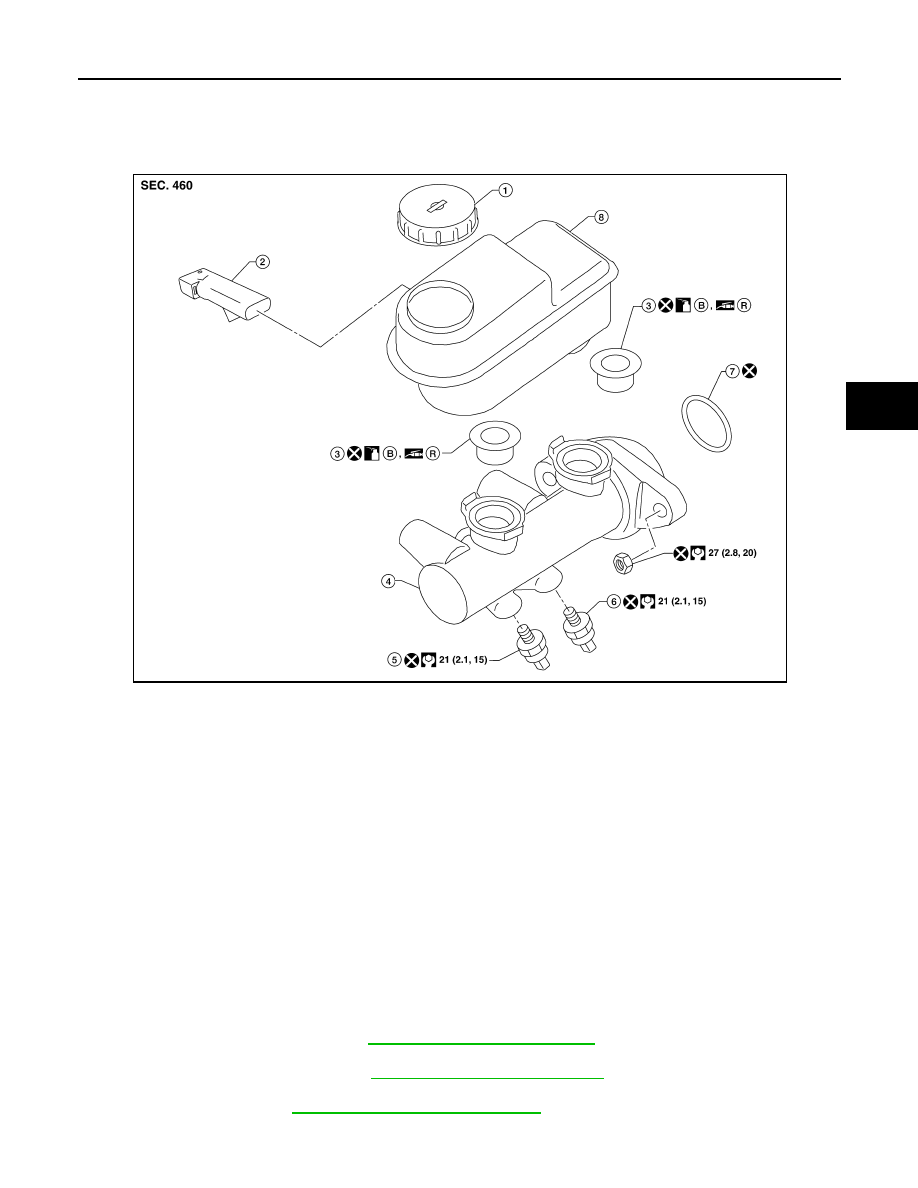
Removal and Installation
INFOID:0000000005147909
REMOVAL
CAUTION:
• Be careful not to splash brake fluid on painted areas; it may cause paint damage. If brake fluid is
splashed on painted areas, wash it away with water immediately.
• Before removing brake master cylinder, depress the brake pedal 5-6 times with the key OFF to
deplete vacuum in the booster.
1. Remove brake reservoir cap.
2. Disconnect harness connectors for fluid level sensor, front and rear pressure sensors.
3. Using suitable tool, disconnect brake tube from master cylinder assembly.
4. Remove master cylinder assembly nuts, and remove master cylinder assembly.
INSTALLATION
Installation is in the reverse order of removal.
• Refill brake fluid and bleed air. Refer to
BR-17, "Bleeding Brake System"
.
CAUTION:
• Refill with new brake fluid. Refer to
MA-13, "Fluids and Lubricants"
.
• Do not reuse drained brake fluid.
• Adjust brake pedal. Refer to
BR-15, "Inspection and Adjustment"
.
1.
Reservoir cap
2.
Fluid level sensor
3.
Grommet
4.
Master cylinder assembly
5.
Front pressure sensor
6.
Rear pressure sensor
7.
Seal
8.
Reservoir tank
B.
Brake fluid
R.
Rubber grease
AWFIA0415GB
BR-26
< ON-VEHICLE REPAIR >
BRAKE BOOSTER
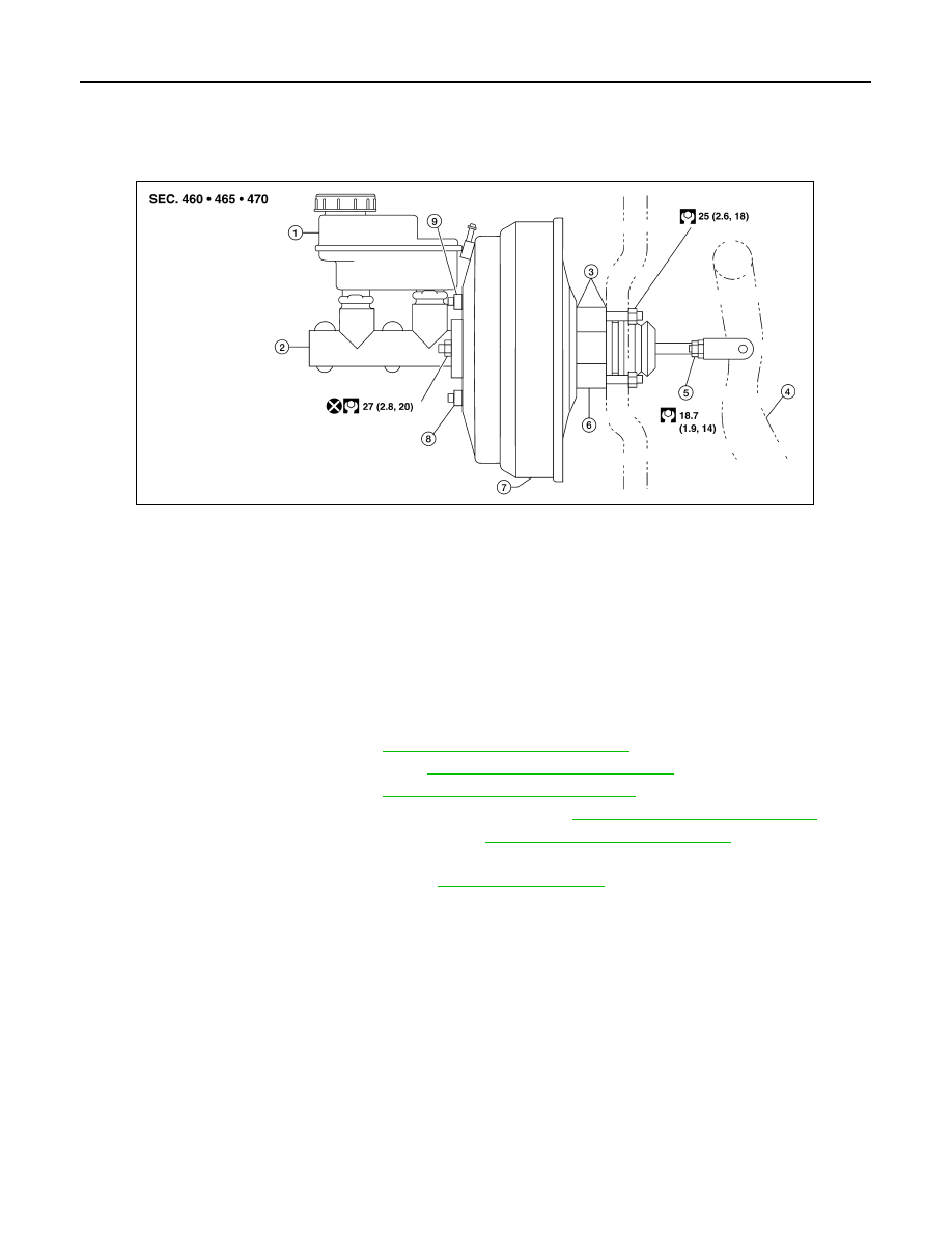
BRAKE BOOSTER
Removal and Installation
INFOID:0000000005147910
CAUTION:
• Be careful not to deform or bend brake piping while removing and installing brake booster.
• Replace clevis pin if it is damaged.
• Be careful not to damage brake booster stud bolt threads. If brake booster is tilted or inclined during
installation, dash panel may damage the threads.
• Attach the check valve in the correct direction.
REMOVAL
1. Remove engine room cover. Refer to
EM-24, "Removal and Installation"
2. Remove engine air duct assembly. Refer to
EM-25, "Removal and Installation"
.
3. Remove cowl top extension. Refer to
EXT-18, "Removal and Installation"
4. Remove master cylinder assembly from brake booster. Refer to
BR-25, "Removal and Installation"
.
5. Remove vacuum hose from brake booster. Refer to
BR-28, "Removal and Installation"
6. Disconnect active boost and delta stroke sensor harness connectors from brake booster.
7. Remove instrument lower panel LH. Refer to
8. Remove brake pedal to clevis attachment snap pin and clevis pin from inside the vehicle.
9. Remove brake booster to brake pedal assembly nuts.
10. Reposition the A/C line out of the way.
11. Remove brake booster and spacer block from dash panel.
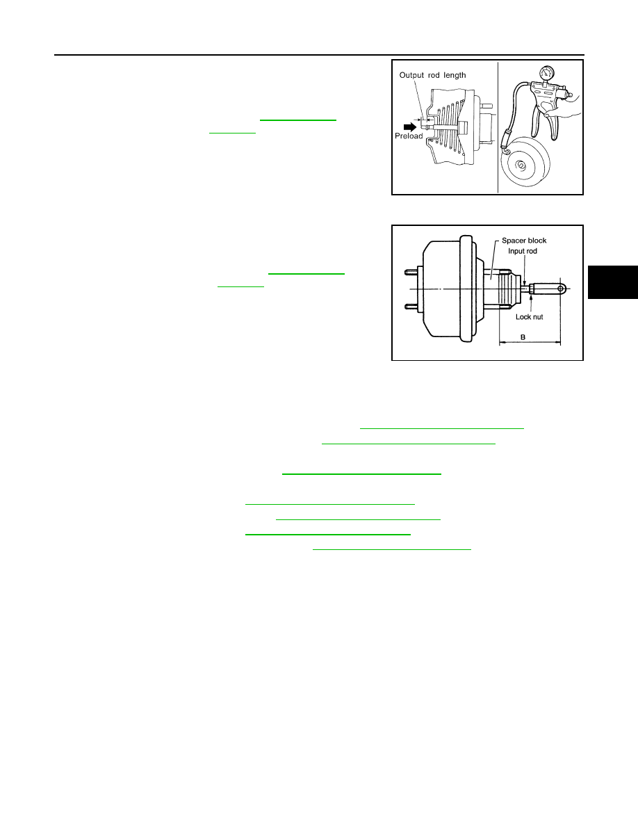
INSPECTION AFTER REMOVAL
Output Rod Length Inspection
1.
Reservoir tank
2.
Master cylinder assembly
3.
Gasket
4.
Brake pedal
5.
Lock nut
6.
Spacer block
7.
Brake booster
8.
Active booster
9.
Delta stroke sensor
AWFIA0416GB
BRAKE BOOSTER
BR-27
< ON-VEHICLE REPAIR >
C
D
E
G
H
I
J
K
L
M
A
B
BR
N
O
P
1. Using a hand vacuum pump, apply a vacuum of – 66.7 kPa (–
500 mmHg, –19.69 inHg) to brake booster.
2. Check output rod length.
INSTALLATION
1. Loosen lock nut to adjust input rod length so that the length (B)
is set at the specified value.
2. After adjusting length (B), temporarily tighten lock nut and install
brake booster and spacer block.
• Install the gaskets and spacer block between brake booster
and dash panel.
3. Connect brake pedal to clevis on the input rod.
4. Install brake booster to brake pedal assembly nuts and tighten
to the specified torque.
5. Connect active boost and delta stroke sensor harness connectors to brake booster.
6. Connect vacuum hose to brake booster.
7. Install master cylinder assembly to brake booster. Refer to
BR-25, "Removal and Installation"
.
8. Adjust the height and play of brake pedal. Refer to
BR-15, "Inspection and Adjustment"
9. Tighten lock nut of input rod to specification.
10. Install instrument lower panel LH. Refer to
IP-14, "Removal and Installation"
.
11. Secure A/C line into clips.
12. Install cowl top extension. Refer to
EXT-18, "Removal and Installation"
.
13. Install engine air duct assembly. Refer to
EM-25, "Removal and Installation"
.
14. Install engine room cover. Refer to
EM-24, "Removal and Installation"
.
15. Refill with new brake fluid and bleed air. Refer to
BR-17, "Bleeding Brake System"
Output rod length
: Refer to
SBR208E
Input rod length (B)
: Refer to
WFIA0382E
Нет комментариевНе стесняйтесь поделиться с нами вашим ценным мнением.
Текст