Infiniti QX56 (JA60). Manual — part 117

BR-28
< ON-VEHICLE REPAIR >
VACUUM LINES
VACUUM LINES
Removal and Installation
INFOID:0000000005147911
REMOVAL
1. Remove engine room cover. Refer to
EM-24, "Removal and Installation"
2. Disconnect vacuum hose from hose clip.
3. Release clamps and disconnect vacuum hose.
4. Remove check valve from brake booster.
INSTALLATION
Installation is in the reverse order of removal.
CAUTION:
• Insert vacuum hose for at least 24 mm (0.94 in).
• Do not use lubricating oil during assembly.
1.
Hose clip
2.
Clamp
3.
Vacuum hose
4.
Check valve
LFIA0216E
SBR225B
FRONT DISC BRAKE
BR-29
< ON-VEHICLE REPAIR >
C
D
E
G
H
I
J
K
L
M
A
B
BR
N
O
P
FRONT DISC BRAKE
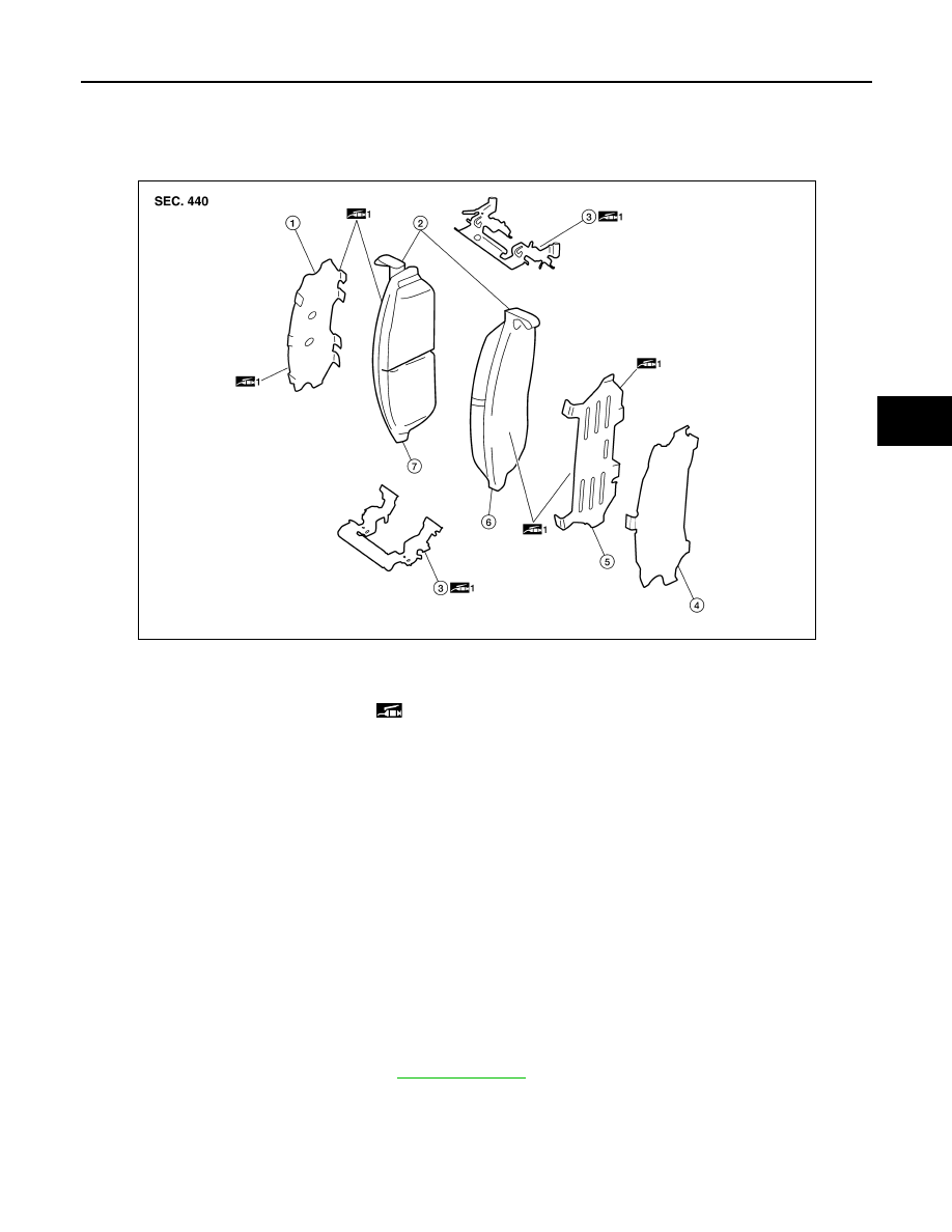
Exploded View of Brake Pads
INFOID:0000000005147912
Removal and Installation of Brake Pads
INFOID:0000000005147913
WARNING:
Clean dust on caliper and brake pad with a vacuum dust collector to minimize the hazard of air borne
particles or other materials.
CAUTION:
• While removing cylinder body, do not depress brake pedal because piston will pop out.
• It is not necessary to remove bolts on torque member and brake hose except for disassembly or
replacement of caliper assembly. In this case, hang cylinder body with a wire so as not to stretch
brake hose.
• Do not damage piston boot.
• If any shim is subject to serious corrosion, replace it with a new one.
• Always replace shim and shim cover as a set when replacing brake pads.
• Keep rotor free from brake fluid.
• Burnish the brake pads and disc rotor mutually contacting surfaces, after refinishing or replacing
rotors, after replacing pads, or if a soft pedal occurs at very low mileage.
REMOVAL
1. Remove front wheel and tires. Refer to
.
2. Partially drain some brake fluid from the reservoir.
3. Remove the sliding pin bolts.
1.
Inner multi-layered shim
2.
Pad wear sensor
3.
Pad retainer
4.
Outer shim cover
5.
Outer shim
6.
Outer pad
7.
Inner pad
1: Molykote M-77 grease
AWFIA0291GB

BR-30
< ON-VEHICLE REPAIR >
FRONT DISC BRAKE
4. Hang cylinder body with a wire, and remove pads, pad retainers,
shims, and shim cover from torque member.
CAUTION:
When removing the pad retainer from the torque member,
lift it in the direction indicated by the arrow as shown so
that it does not deform.
INSTALLATION
1. Push pistons in using suitable tool.
CAUTION:
By pushing in pistons, brake fluid returns to master cylinder reservoir tank. Watch the brake fluid
level in the reservoir tank.
NOTE:
Using a suitable tool, makes it easier to push in the pistons.
2. Apply Molykote M-77 grease or equivalent to between shim cover and shim. Install outer shim, outer shim
cover to inner pad, and inner multi-layered shim to outer pad.
3. Apply Molykote M-77 grease or equivalent to between pad retainer and pad. Install pad retainers and pads
to torque member.
4. Apply Molykote M-77 grease or equivalent to the piston face.
Install pad return lever securely to pad wear sensor as shown.
CAUTION:
• Securely assemble pad retainers so that they are not
being lifted up from torque member.
• Both inner and outer pads have a pad return system on
the pad retainer. Install pad return lever securely to pad
wear sensor.
5. Install pads to cylinder body.
6. Install cylinder body to torque member.
CAUTION:
In the case of replacing a pad with new one, check the brake fluid level in the reservoir tank
because brake fluid returns to reservoir tank when pressing piston in.
NOTE:
Use a suitable tool to easily press piston.
7. Apply rubber grease and install sliding pin bolts, and tighten to the specified torque. Refer to
"Exploded View of Brake Caliper"
8. Check front disc brake for drag.
9. Install front wheel and tires. Refer to
Brake Burnishing Procedure
INFOID:0000000005147914
Burnish contact surfaces between disc rotors and pads according to following procedure after refinishing or
replacing rotors, after replacing pads, or if a soft pedal occurs at very low mileage.
CAUTION:
• Be careful of vehicle speed because the brake does not operate easily until pad and disc rotor are
securely seated.
• Only perform this procedure under safe road and traffic conditions. Use extreme caution.
1. Drive vehicle on straight, flat road.
2. Depress brake pedal with the power to stop vehicle within 3 to 5 seconds until the vehicle stops.
3. Drive without depressing brake for a few minutes to cool the brake.
4. Repeat steps 1 through 3 until pad and disc rotor are securely seated.
SBR556E
SBR557E

FRONT DISC BRAKE
BR-31
< ON-VEHICLE REPAIR >
C
D
E
G
H
I
J
K
L
M
A
B
BR
N
O
P
Exploded View of Brake Caliper
INFOID:0000000005147915
Removal and Installation of Brake Caliper and Rotor
INFOID:0000000005147916
WARNING:
Clean dust on caliper and brake pad with a vacuum dust collector to minimize the hazard of air borne
particles or other materials.
CAUTION:
• While removing cylinder body, do not depress brake pedal because piston will pop out.
• Do not damage piston boot.
• Keep rotor free from brake fluid.
• Refill with new specified brake fluid.
• Burnish brake contact surface after refinishing or replacing rotors, after replacing pads, or it a soft
pedal occurs at very low mileage. Refer to
BR-30, "Brake Burnishing Procedure"
.
REMOVAL
1. Remove front wheel and tire. Refer to
2. Fasten disc rotor using wheel nut.
3. Remove brake reservoir cap.
4. Remove union bolt, and then disconnect brake hose from caliper assembly.
NOTE:
Discard the copper washers, do not reuse.
1.
Sliding pin bolt
2.
Bleed valve
3.
Cap
4.
Union bolt
5.
Brake hose
6.
Copper washer
7.
Torque member bolt
8.
Sliding pin boot
9.
Torque member
10. Washers
11. Bushing
12. Sliding pin
13. Piston boot
14. Piston
15. Piston seal
16. Cylinder body
Brake fluid
1: Molykote M-77 grease
2: Rubber grease
AWFIA0573GB
Нет комментариевНе стесняйтесь поделиться с нами вашим ценным мнением.
Текст