Infiniti QX56 (JA60). Manual — part 114
BR-16
< ON-VEHICLE MAINTENANCE >
BRAKE PEDAL
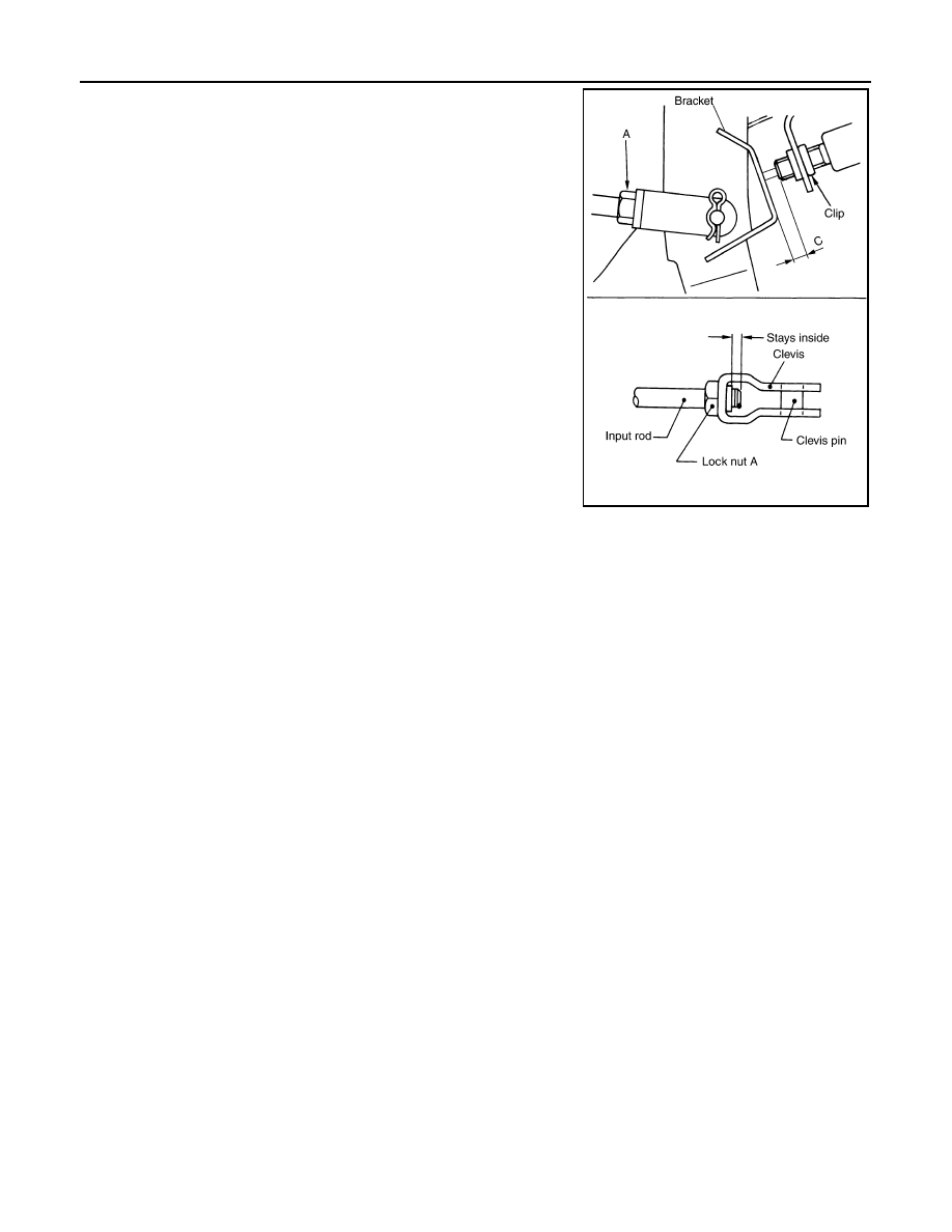
2. Loosen lock nut (A) on the input rod, then turn input rod to adjust
the brake pedal to the specified height. When finished adjusting,
tighten the lock nut (A) to specification.
CAUTION:
Make sure that the screw portion of the end of input rod is
located inside the clevis.
3. With the brake pedal pulled up and held by hand, press the stop
lamp switch and the ASCD cancel switch in until the threaded
ends contact the brake pedal bracket.
4. With the threaded ends of the stop lamp switch and ASCD
switch contacting the pedal bracket, turn the switches 45
° clock-
wise to lock in place. Check that the stop lamp switch and ASCD
cancel switch threaded end to brake pedal bracket gap (C) is
within specifications.
CAUTION:
Make sure that the gap (C) between the brake pedal bracket
and stop lamp switch and ASCD cancel switch threaded
ends are within specification.
5. Check the brake pedal for smooth operation.
CAUTION:
Make sure that the stop lamp goes off when the brake pedal
is released.
6. Start the engine and check the height of the brake pedal when depressing it.
Lock nut (A)
: 18.7 N·m (1.9 kg-m, 14 ft-lb)
PFIA0436E
BRAKE FLUID
BR-17
< ON-VEHICLE MAINTENANCE >
C
D
E
G
H
I
J
K
L
M
A
B
BR
N
O
P
BRAKE FLUID
On Board Inspection
INFOID:0000000005147901
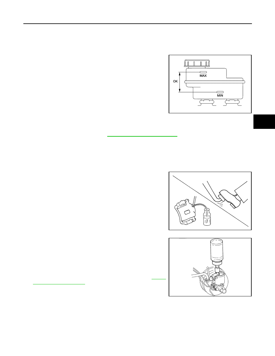
LEVEL CHECK
• Make sure the fluid level in reservoir tank is between MAX and MIN
lines as shown.
• Visually check around reservoir tank for fluid leaks.
• If fluid level is excessively low, check brake system for leaks.
• If brake warning lamp remains illuminated after parking brake
pedal is released, check brake system for fluid leaks.
Drain and Refill
INFOID:0000000005147902
CAUTION:
• Refill with new brake fluid. Refer to
MA-13, "Fluids and Lubricants"
• Do not reuse drained brake fluid.
• Do not let brake fluid splash on the painted surfaces of the body. This might damage the paint, so if
splashing it, immediately wipe off the area and wash away with water.
• Before servicing, disconnect ABS actuator and electric unit (control unit) connector or battery nega-
tive terminal.
1. Connect a vinyl tube to each bleed valve.
2. Depress brake pedal, loosen each bleed valve, and gradually
remove brake fluid.
3. Make sure there is no foreign material in reservoir tank, and refill
with new brake fluid.
4. Rest foot on brake pedal. Loosen bleed valve. Slowly depress
pedal until it stops. Tighten bleed valve. Release brake pedal.
Repeat this process a few times, then pause to add new brake
fluid to master cylinder. Continue until new brake fluid flows out
of the bleed valve.
Bleed the air out of the brake hydraulic system. Refer to
.
Bleeding Brake System
INFOID:0000000005147903
CAUTION:
While bleeding, pay attention to master cylinder fluid level.
1. Turn ignition switch OFF and disconnect ABS actuator and electric unit (control unit) connector or battery
negative terminal.
2. Connect a vinyl tube to the rear right bleed valve.
LFIA0225E
SBR419C
SBR995
BR-18
< ON-VEHICLE MAINTENANCE >
BRAKE FLUID
3. Fully depress brake pedal 4 to 5 times.
4. With brake pedal depressed, loosen bleed valve to let the air out, and then tighten it immediately.
5. Repeat steps 3 and 4 until no more air comes out.
6. Tighten bleed valve to the specified torque. Refer to
BR-31, "Exploded View of Brake Caliper"
(front disc
BR-35, "Exploded View of Brake Caliper"
(rear disc brake).
7. Repeat steps 2 through 6 at each wheel, with master cylinder reservoir tank filled at least half way, bleed-
ing air in order from the front left, rear left, and front right bleed valves.
BRAKE PEDAL
BR-19
< ON-VEHICLE REPAIR >
C
D
E
G
H
I
J
K
L
M
A
B
BR
N
O
P
ON-VEHICLE REPAIR
BRAKE PEDAL
Removal and Installation
INFOID:0000000005147904
REMOVAL
CAUTION:
• Before removal and installation, the accelerator and brake pedals must be in the forward most posi-
tion (closest to the floor). This is to align the base position of the accelerator and brake pedals.
• Do not disassemble the brake pedal adjusting mechanism.
• Avoid damage from dropping the brake pedal assembly during handling.
• Keep the brake pedal assembly away from water.
1. Remove the lower instrument panel LH. Refer to
IP-17, "Removal and Installation"
.
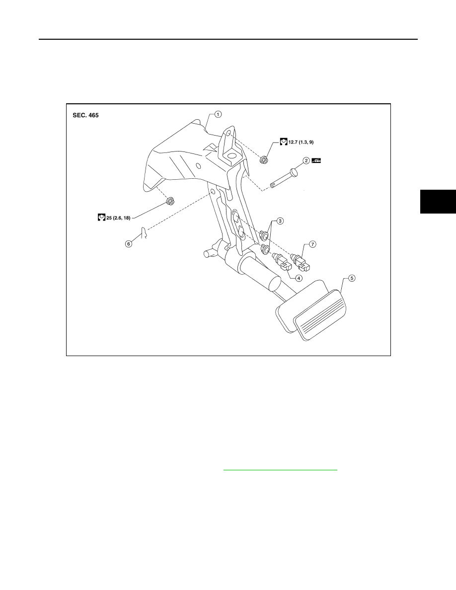
2. Remove the stop lamp switch and ASCD cancel switch from the pedal assembly.
1.
Brake pedal assembly
2.
Clevis pin
3.
Clip
4.
Stop lamp switch
5.
Pedal pad
6.
Snap pin
7.
ASCD cancel switch
AWFIA0582GB
Нет комментариевНе стесняйтесь поделиться с нами вашим ценным мнением.
Текст