Infiniti QX56 (JA60). Manual — part 801
RSU-14
< REMOVAL AND INSTALLATION >
REAR SUSPENSION MEMBER
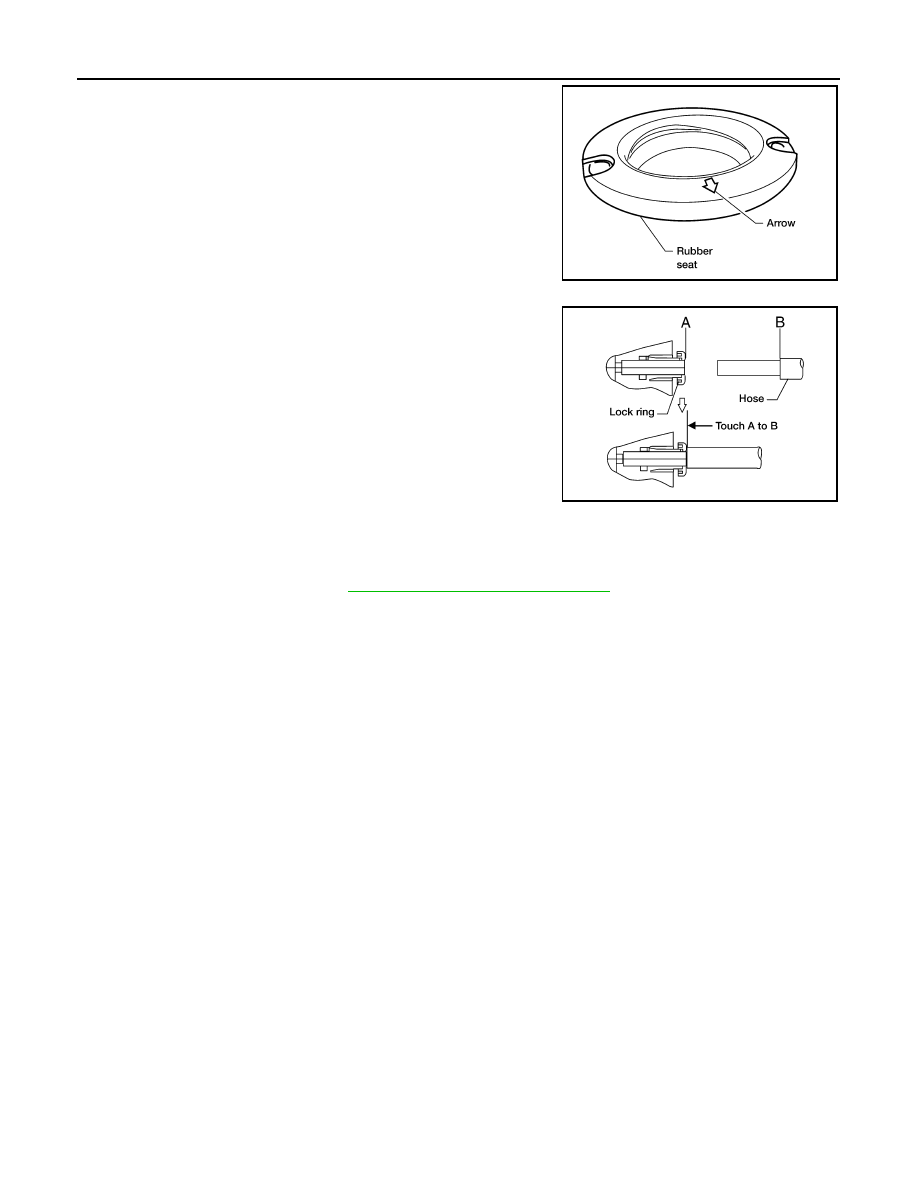
• When installing the upper and lower rubber seats for the rear coil
springs, the arrow embossed on the rubber seats must point out
toward the wheel and tire assembly.
• To connect the rear load leveling air suspension hoses, the lock
ring must be fully seated in the fitting. Insert the hose (B) into the
lock ring (A) until the lock ring (A) is touching the hose (B) as
shown. Pull on the hose to check that it is securely inserted.
• Perform the final tightening of the nuts and bolts for the links (rubber bushing) under unladen condition
(unladen condition means that the fuel tank, engine coolant and lubricants are at the full specification, and
the spare tire, jack, hand tools, and mats are in their designated positions) with the tires on level ground.
• Check the wheel alignment. Refer to
RSU-6, "Wheel Alignment Inspection"
.
LEIA0076E
LEIA0078E
SHOCK ABSORBER
RSU-15
< REMOVAL AND INSTALLATION >
C
D
F
G
H
I
J
K
L
M
A
B
RSU
N
O
P
SHOCK ABSORBER
Removal and Installation
INFOID:0000000005148133
REMOVAL
1. Remove the wheel and tire assembly using power tool. Refer to
.
2. Use CONSULT-III “EXHAUST SOLENOID” active test to release the air pressure from the rear load level-
ing air suspension system.
3. Remove the four clips and remove the rear fender protector, front.
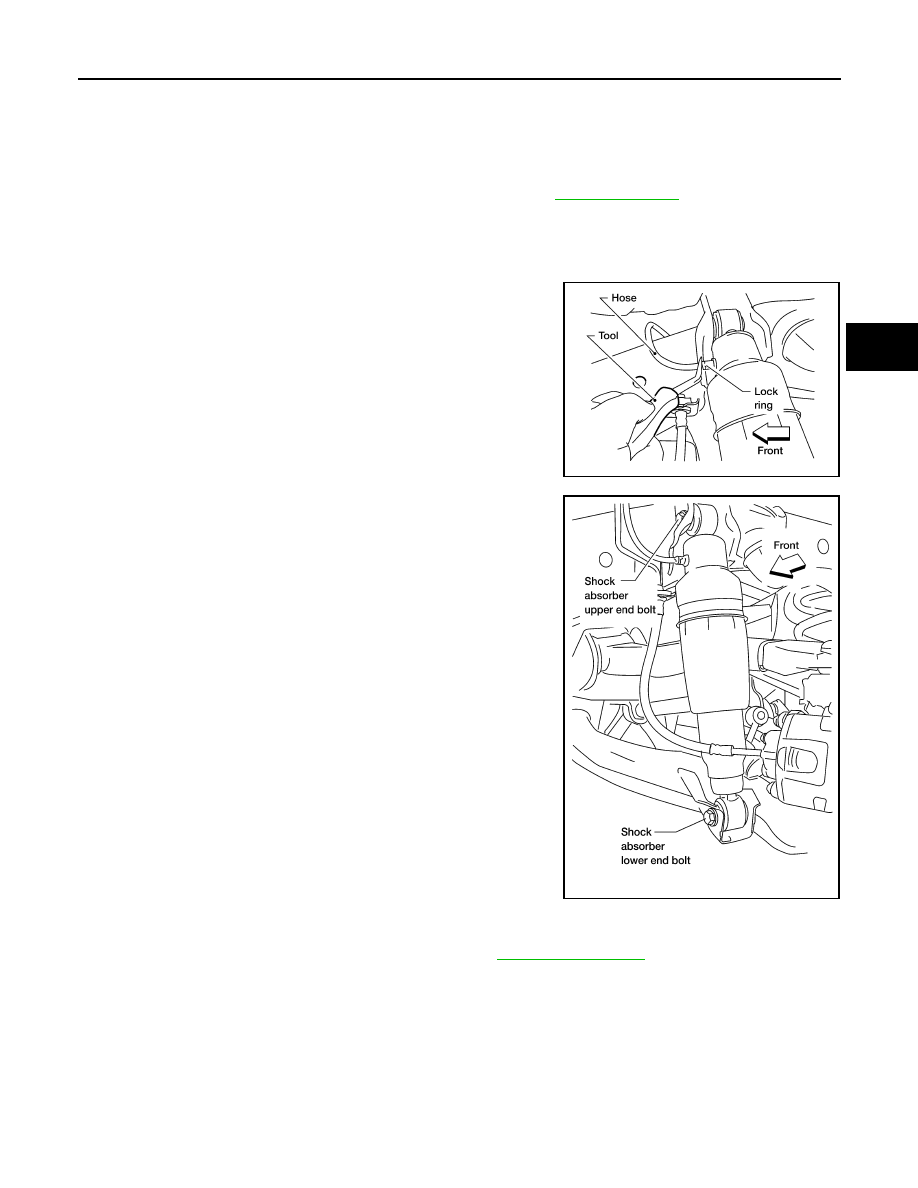
4. Disconnect the rear load leveling air suspension hose from the
shock absorber.
• To disconnect the hose, push in on the lock ring using a suit-
able tool and pull the air hose out.
5. Remove the shock absorber upper and lower end bolts using
power tool.
6. Remove the shock absorber.
CAUTION:
Do not damage the rubber boot on the shock absorber.
INSTALLATION
Installation is in the reverse order of removal.
• Tighten the shock absorber bolts to specification. Refer to
.
INSPECTION AFTER INSTALLATION
• Check the shock absorber for any air leaks or damage to the rubber boot.
• Check the shock absorber for smooth operation through a full stroke, both compression and extension.
• Check piston rod for cracks, deformation or other damage and replace if necessary.
Disposal
INFOID:0000000005369243
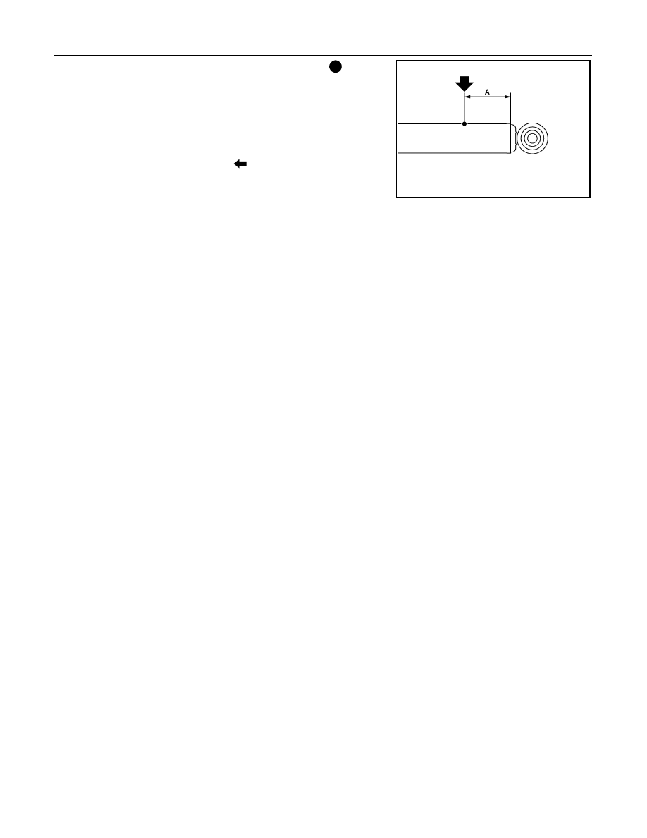
1. Set shock absorber horizontally with the piston rod fully extended.
LEIA0081E
LEIA0082E
RSU-16
< REMOVAL AND INSTALLATION >
SHOCK ABSORBER
2. Drill 2 – 3 mm (0.08 – 0.12 in) hole at the position ( ) from top
as shown in the figure to release gas gradually.
CAUTION:
• Wear eye protection (safety glasses).
• Wear gloves.
• Be careful with metal chips or oil blown out by the com-
pressed gas.
NOTE:
• Drill vertically in this direction (
).
• Directly to the outer tube avoiding brackets.
• The gas is clear, colorless, odorless, and harmless.
3. Position the drilled hole downward and drain oil by moving the piston rod several times.
CAUTION:
Dispose of drained oil according to the law and local regulations.
A
: 20 – 30 mm (0.79 – 1.18 in)
JPEIA0161ZZ
SUSPENSION ARM
RSU-17
< REMOVAL AND INSTALLATION >
C
D
F
G
H
I
J
K
L
M
A
B
RSU
N
O
P
SUSPENSION ARM
Removal and Installation
INFOID:0000000005148134
REMOVAL
1. Remove the rear suspension member assembly using power tool. Refer to
.
NOTE:
It is necessary to remove the rear suspension member to remove the front upper bolt from the suspension
arm.
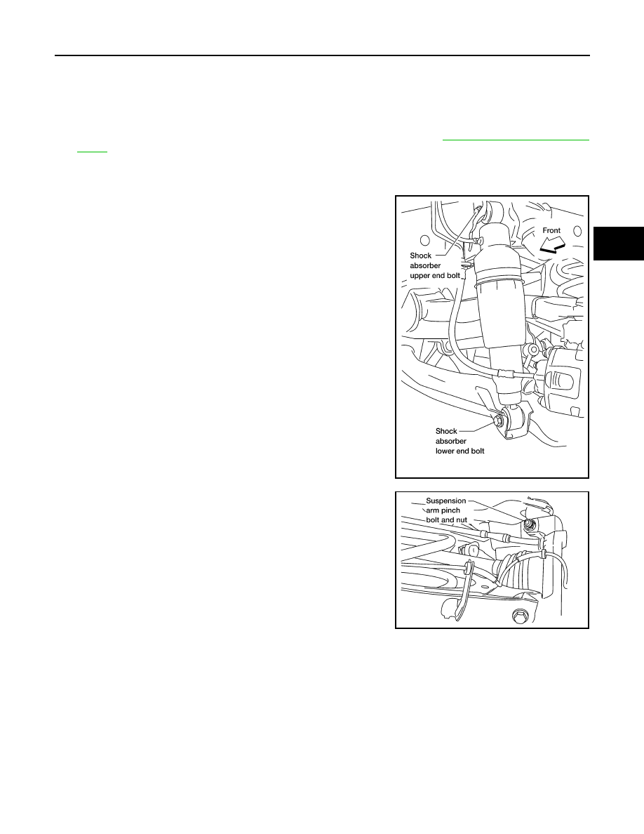
2. Remove the shock absorber upper end bolt.
3. Remove the suspension arm upper nuts and bolts on the sus-
pension member side using power tool.
4. Remove the suspension arm pinch bolt and nut on the knuckle
side using power tool.
5. Disconnect the suspension arm from the knuckle using a soft
hammer.
CAUTION:
Do not damage the ball joint with the soft hammer.
6. Remove the suspension arm.
INSPECTION AFTER REMOVAL
• Check the suspension arm for damage, cracks, deformation and replace if necessary.
• Check the rubber bushing for damage, cracks and deformation. Replace suspension arm assembly if neces-
sary.
• Before checking, turn the ball joint at least 10 revolutions so that the ball joint is properly broken in.
LEIA0082E
LEIA0087E
Нет комментариевНе стесняйтесь поделиться с нами вашим ценным мнением.
Текст