Infiniti QX56 (JA60). Manual — part 799
RSU-6
< ON-VEHICLE MAINTENANCE >
REAR SUSPENSION ASSEMBLY
ON-VEHICLE MAINTENANCE
REAR SUSPENSION ASSEMBLY
On-Vehicle Inspection and Service
INFOID:0000000005148129
Check all of the component mountings for any excessive looseness, or back lash. Check the components for
any excessive wear, damage, or abnormal conditions. Repair or replace the components as necessary.
SHOCK ABSORBER INSPECTION
• Check the shock absorbers for any air leaks or damage, and replace as necessary.
• Check the hoses for any air leaks or damage, and replace as necessary.
Wheel Alignment Inspection
INFOID:0000000005148130
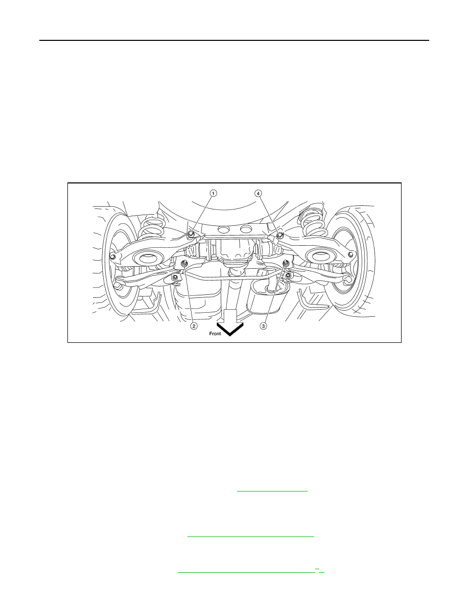
Rear Wheel Alignment Adjusting Bolts
PRELIMINARY INSPECTION
WARNING:
Always adjust the alignment with the vehicle on a flat surface. Use CONSULT-III “EXHAUST SOLE-
NOID” active test to release the air pressure from the rear load leveling air suspension system.
NOTE:
If alignment is out of specification, inspect and replace any damaged or worn rear suspension parts before
making any adjustments.
1. Check and adjust the wheel alignment with the vehicle under unladen conditions. “Unladen conditions”
means that the fuel, coolant, and lubricant are full; and that the spare tire, jack, hand tools and mats are in
their designated positions.
2. Check the tires for incorrect air pressure and excessive wear.
3. Check the wheels for runout and damage. Refer to
4. Check the wheel bearing axial end play.
5. Check the shock absorbers. Refer to
RSU-15, "Removal and Installation"
6. Check each mounting point of the suspension components for any excessive looseness or damage.
7. Check each link, arm, and the rear suspension member for any damage.
8. Check the vehicle height. Refer to
RSU-30, "Wheelarch Height (Unladen*
WEIA0102E
1.
Rear lower link adjusting bolt, LH
2.
Front lower link adjusting bolt, LH
3.
Front lower link adjusting bolt, RH
4.
Rear lower link adjusting bolt, RH
Axial end play
: 0 mm (0 in)
REAR SUSPENSION ASSEMBLY
RSU-7
< ON-VEHICLE MAINTENANCE >
C
D
F
G
H
I
J
K
L
M
A
B
RSU
N
O
P
• If vehicle height is not within
± 10 mm (0.39 in) of the specification, perform the control unit initialization
RSU-26, "Initialization Procedure"
GENERAL INFORMATION AND RECOMMENDATIONS
1. A Four-Wheel Thrust Alignment should be performed.
• This type of alignment is recommended for any NISSAN vehicle.
• The four-wheel “thrust” process helps ensure that the vehicle is properly aligned and the steering wheel
is centered.
• The alignment machine itself should be capable of accepting any NISSAN vehicle.
• The alignment machine should be checked to ensure that it is level.
2. Make sure the alignment machine is properly calibrated.
• Your alignment machine should be regularly calibrated in order to give correct information.
• Check with the manufacturer of your specific alignment machine for their recommended Service/Cali-
bration Schedule.
THE ALIGNMENT PROCESS
IMPORTANT: Use only the alignment specifications listed in this Service Manual. Refer to
1. When displaying the alignment settings, many alignment machines use “indicators”: (Green/red, plus or
minus, Go/No Go). Do NOT use these indicators.
• The alignment specifications programmed into your alignment machine that operate these indicators
may not be correct.
• This may result in an ERROR.
2. Some newer alignment machines are equipped with an optional “Rolling Compensation” method to “com-
pensate” the sensors (alignment targets or head units). Do NOT use this “Rolling Compensation”
method.
• Use the “Jacking Compensation” method. After installing the alignment targets or head units, raise the
vehicle and rotate the wheels 1/2 turn both ways.
• See Instructions in the alignment machine you are using for more information.
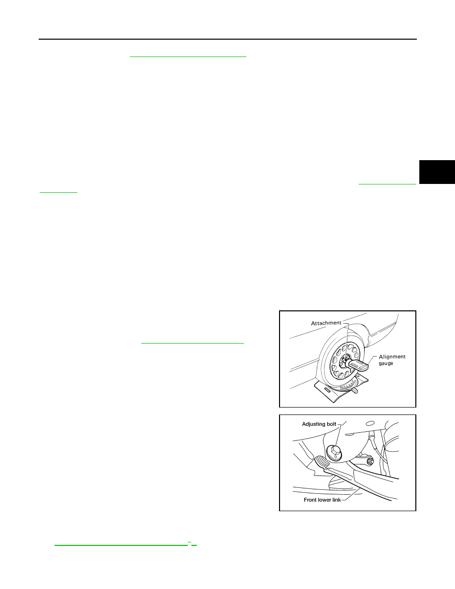
CAMBER
1. Measure camber of both the right and left wheels with a suitable
alignment gauge and adjust as necessary to specification.
2. If outside of the specified value, adjust the camber using the
adjusting bolt in the front lower link.
CAUTION:
After adjusting the camber then check the toe-in.
NOTE:
Camber changes about 0
° 5' with each graduation of the adjust-
ing bolt.
3. Tighten the adjusting bolt nuts to specification.
TOE-IN
1. Bounce the rear of the vehicle up and down two to three times to stabilize the vehicle height. Refer to
RSU-30, "Wheelarch Height (Unladen*
2. Push the vehicle straight ahead about 5 m (16 ft).
Camber
: Refer to
SRA096A
LEIA0041E

RSU-8
< ON-VEHICLE MAINTENANCE >
REAR SUSPENSION ASSEMBLY
3. Put a mark on the base line of the tread (rear side) of both of the
tires at the same height as the center of the hub. This will be the
measuring points.
4. Measure the distance (A) from rear side across from tire to tire.
5. Push the vehicle slowly ahead to rotate the wheels 180
° (a half
turn).
If the wheels are rotated more than 180
° (a half turn), then
repeat the above steps. Never push the vehicle backward.
6. Measure the distance (B) from front side across from tire to tire.
7. If the toe-in is outside the specified value, adjust the toe-in using
the adjusting bolt in the rear lower link.
CAUTION:
Be sure to adjust equally on RH and LH sides using the
adjusting bolt.
NOTE:
Toe changes about 1.5 mm (0.059 in) [one side] with each grad-
uation of the adjusting bolt.
8. Tighten the adjusting bolt nuts to specification.
SFA614B
Total toe-in
: Refer to
SFA234AC
LEIA0009E

REAR SUSPENSION ASSEMBLY
RSU-9
< ON-VEHICLE REPAIR >
C
D
F
G
H
I
J
K
L
M
A
B
RSU
N
O
P
ON-VEHICLE REPAIR
REAR SUSPENSION ASSEMBLY
Component
INFOID:0000000005148131
Rear Suspension
AWEIA0143GB
1.
Seat belt latch anchor
2.
Stabilizer bar bushing
3.
Stabilizer bar clamp
4.
Stabilizer bar
5.
Connecting rod
6.
Front lower link
7.
Knuckle
8.
Bushing
9.
Rear lower link
10. Shock absorber
11. Suspension arm
12. Lower rubber seat
Нет комментариевНе стесняйтесь поделиться с нами вашим ценным мнением.
Текст