Infiniti QX56 (JA60). Manual — part 800
RSU-10
< ON-VEHICLE REPAIR >
REAR SUSPENSION ASSEMBLY
Rear Load Leveling Air Suspension System
13. Coil spring
14. Upper rubber seat
15. Rear suspension member
16. Spare tire bracket
17. Bound bumper
Front
AWEIA0054GB
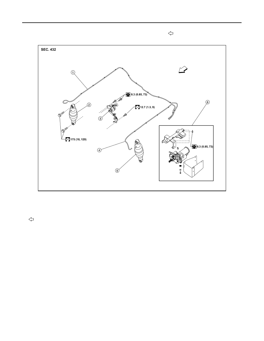
1.
Rear load leveling air suspension
hose, RH
2.
Shock absorber, RH
3.
Height sensor
4.
Rear load leveling air suspension
hose, LH
5.
Shock absorber, LH
6.
Rear load leveling air suspension
compressor assembly
Front

REAR SUSPENSION MEMBER
RSU-11
< REMOVAL AND INSTALLATION >
C
D
F
G
H
I
J
K
L
M
A
B
RSU
N
O
P
REMOVAL AND INSTALLATION
REAR SUSPENSION MEMBER
Removal and Installation
INFOID:0000000005148132
Rear Suspension
AWEIA0143GB
1.
Seat belt latch anchor
2.
Stabilizer bar bushing
3.
Stabilizer bar clamp
4.
Stabilizer bar
5.
Connecting rod
6.
Front lower link
7.
Knuckle
8.
Bushing
9.
Rear lower link
10. Shock absorber
11. Suspension arm
12. Lower rubber seat

RSU-12
< REMOVAL AND INSTALLATION >
REAR SUSPENSION MEMBER
Rear Load Leveling Air Suspension System
REMOVAL
1. Use the CONSULT-III “EXHAUST SOLENOID” active test to release the air pressure from the rear load
leveling air suspension system.
2. Disconnect the electrical connectors for the height sensor and the rear load leveling air suspension com-
pressor assembly.
3. Unclip the rubber cover to access the rear load leveling air suspension compressor assembly.
4. Disconnect the rear load leveling air suspension hoses at the
rear load leveling air suspension compressor assembly.
• To disconnect the hoses, push in on the lock ring using a suit-
able tool and pull the hose out.
5. Remove both of the rear wheel and tire assemblies using power
tool.
6. Remove the brake caliper without disconnecting the brake
hoses, using power tool. Reposition the brake caliper out of the
way using a suitable wire. Refer to
lation of Brake Caliper and Disc Rotor"
.
CAUTION:
13. Coil spring
14. Upper rubber seat
15. Rear suspension member
16. Spare tire bracket
17. Bound bumper
Front
AWEIA0054GB
1.
Rear load leveling air suspension
hose, RH
2.
Shock absorber, RH
3.
Height sensor
4.
Rear load leveling air suspension
hose, LH
5.
Shock absorber, LH
6.
Rear load leveling air suspension
compressor assembly (includes the
bracket and rubber cover)
Front
LEIA0074E
REAR SUSPENSION MEMBER
RSU-13
< REMOVAL AND INSTALLATION >
C
D
F
G
H
I
J
K
L
M
A
B
RSU
N
O
P
• Do not crimp or stretch the brake hose when repositioning the brake caliper out of the way.
• Do not press brake pedal while the brake caliper is removed.
7. Remove the spare tire.
8. Disconnect the two rear ABS sensor electrical connectors.
9. Remove the two rear drive shafts. Refer to
RAX-10, "Removal and Installation"
.
10. Remove the rear final drive. Refer to
DLN-250, "Removal and Installation"
11. Remove the EVAP canister bolt from the top of the rear suspension member.
12. Disconnect the parking brake cables from the brackets on the rear suspension member.
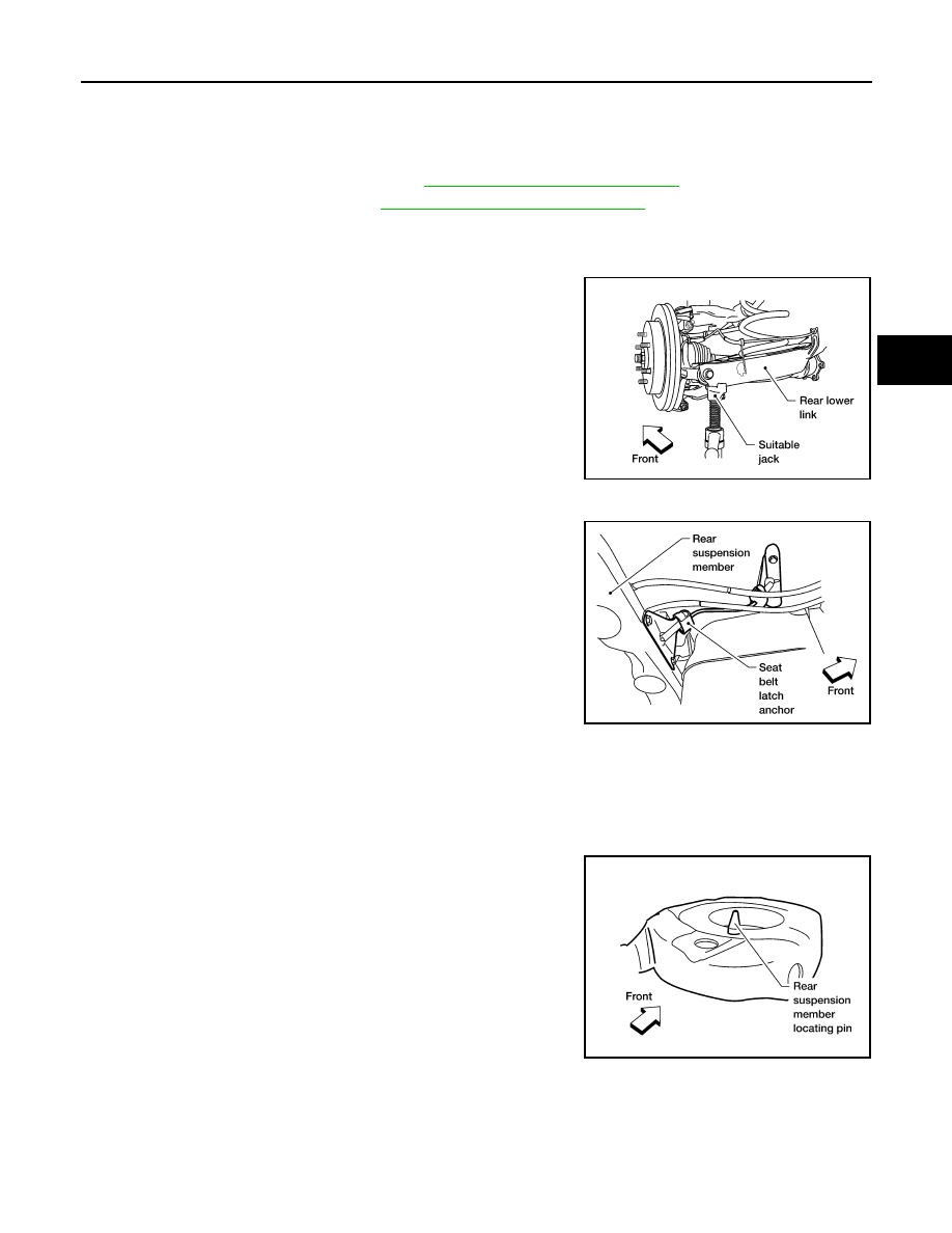
13. Set a suitable jack to support each of the rear lower links and the
coil spring tension.
14. Remove both of the rear lower link outer bolts and lower the jack to remove the rear coil springs.
15. Remove the two bolts to disconnect the seat belt latch anchor
from the rear suspension member.
16. Disconnect both of the connecting rods from the rear stabilizer
bar.
17. Set a suitable jack under the rear suspension member.
18. Remove the six rear suspension member bolts.
19. Slowly lower the jack to remove the rear suspension member,
suspension arm, front and rear lower links and stabilizer bar as
an assembly.
20. If necessary, remove the suspension arm, spare tire bracket,
height sensor, rear load leveling air suspension hoses, stabilizer
bar, knuckle, and front and rear lower links from the rear suspension member.
INSPECTION AFTER REMOVAL
Check the rear suspension member for deformation, cracks, and other damage and replace if necessary.
INSTALLATION
Installation is in the reverse order of removal.
• When raising the rear suspension member assembly, use the
locating pins to align the rear suspension member to the vehicle
body.
LEIA0077E
LEIA0075E
LEIA0083E
Нет комментариевНе стесняйтесь поделиться с нами вашим ценным мнением.
Текст