Infiniti QX56 (JA60). Manual — part 332
REAR FINAL DRIVE
DLN-251
< REMOVAL AND INSTALLATION >
[REAR FINAL DRIVE: R230]
C
E
F
G
H
I
J
K
L
M
A
B
DLN
N
O
P
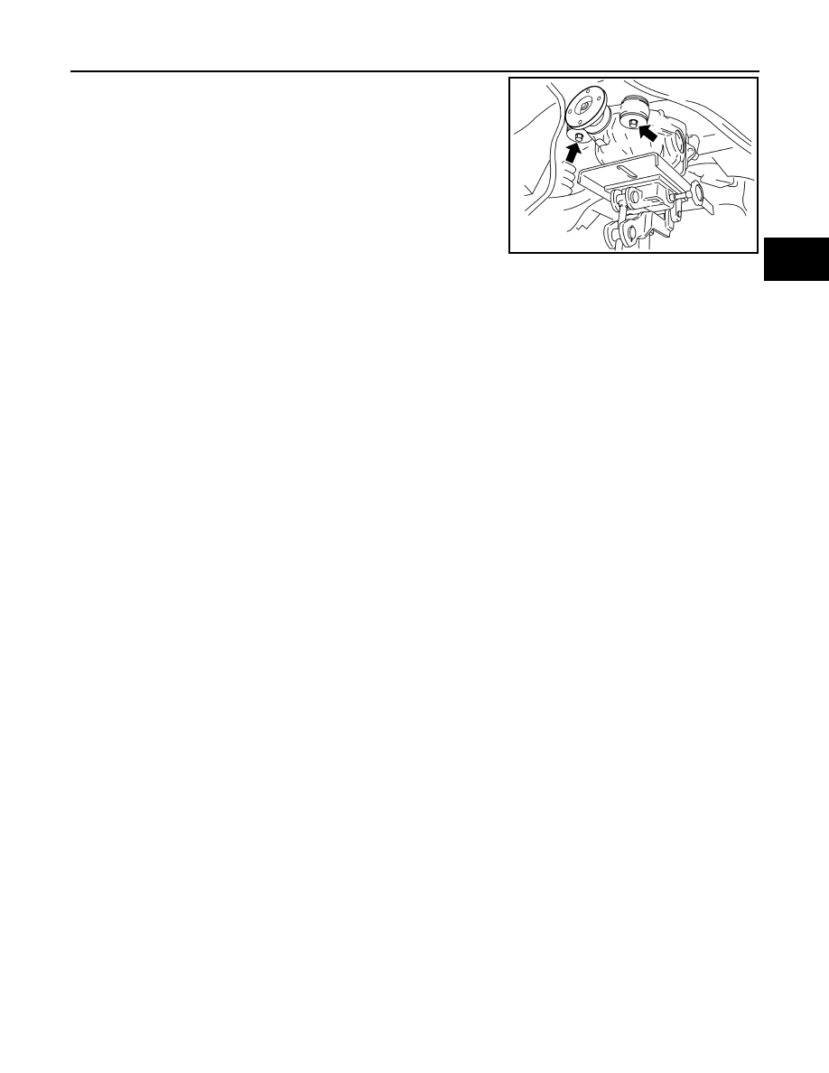
7. Place a suitable jack under the rear final drive assembly.
CAUTION:
Do not place the jack on the carrier cover.
8. Remove the nuts and bolts and remove the rear final drive
assembly.
CAUTION:
Secure rear final drive assembly to the jack while removing
it.
INSTALLATION
Installation is in the reverse order of removal.
CAUTION:
• When installing the breather hose make sure the painted marking on the metal end of breather hose
is to the front of the vehicle and there are no pinched or restricted areas on the breather hose
caused by folding or bending when installing it.
• When installing the breather hose insert the plastic end of the breather hose into the hole in the sus-
pension member.
WDIA0117E
DLN-252
< REMOVAL AND INSTALLATION >
[REAR FINAL DRIVE: R230]
REAR FINAL DRIVE
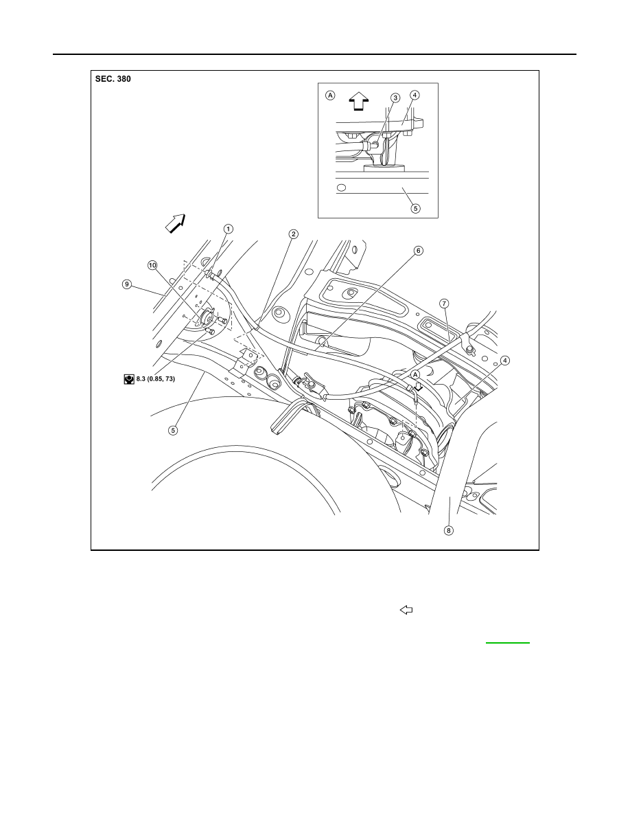
REAR FINAL DRIVE BREATHER
• Fill the rear final drive assembly with differential gear oil after installation. Refer to
ALDIA0210GB
1.
Rear final drive breather hose connector 2.
Plastic clip
3.
Rear final drive breather tube
4.
Rear final drive assembly
5.
Rear suspension member 6.
Rear final drive breather hose
7.
Parking brake cable
8.
Exhaust pipe
9.
Frame (LH)
10. Rear final drive breather hose frame
connector
A.
Close-up view
Front
REAR FINAL DRIVE
DLN-253
< DISASSEMBLY AND ASSEMBLY >
[REAR FINAL DRIVE: R230]
C
E
F
G
H
I
J
K
L
M
A
B
DLN
N
O
P
DISASSEMBLY AND ASSEMBLY
REAR FINAL DRIVE
Disassembly and Assembly
INFOID:0000000005148936
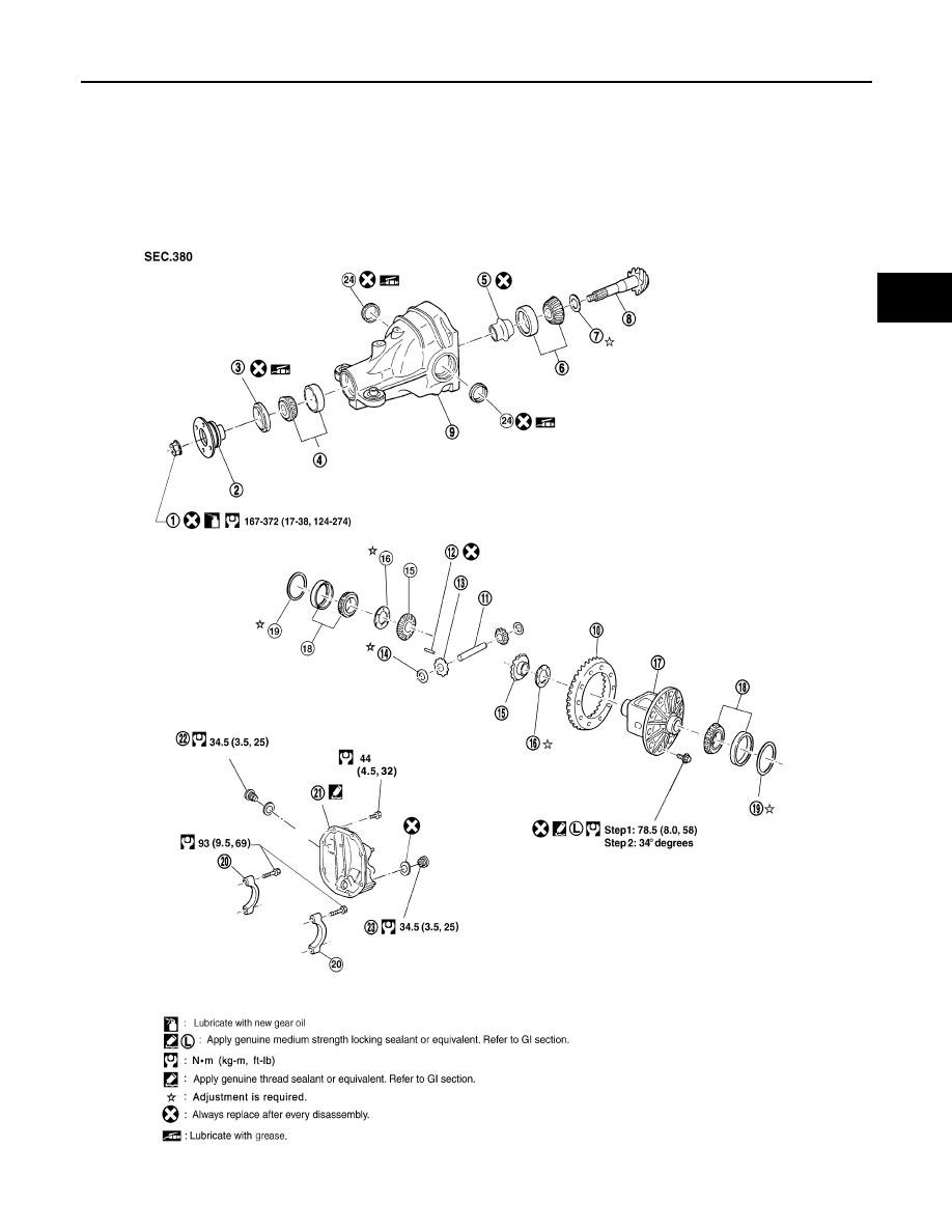
COMPONENTS
WDIA0191E
DLN-254
< DISASSEMBLY AND ASSEMBLY >
[REAR FINAL DRIVE: R230]
REAR FINAL DRIVE
ASSEMBLY INSPECTION AND ADJUSTMENT
• Drain the differential gear oil before inspection and adjustment. Refer to
.
• Remove and install the carrier cover as necessary for inspection and adjustment. Refer to
.
Total Preload Torque
1. Remove the side flanges if necessary. Refer to
DLN-247, "Removal and Installation"
.
CAUTION:
The side flanges must removed in order to measure total preload torque.
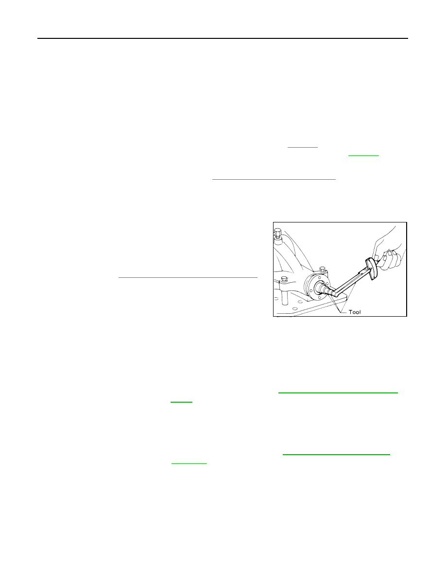
2. Rotate the drive pinion back and forth 2 to 3 times to check for unusual noise and rotation malfunction.
3. Rotate the drive pinion at least 20 times to check for smooth operation of the bearings.
4. Measure the total preload torque using Tool.
NOTE:
Total preload torque = Drive pinion bearing preload torque +
Side bearing preload torque
• If the measured value is out of the specification, check and adjust each part. Adjust the drive pinion
bearing preload torque first, then adjust the side bearing preload torque.
CAUTION:
Select a side bearing adjusting washer for right and left individually.
Drive Gear Runout
1.
Drive pinion lock nut
2.
Companion flange
3.
Front oil seal
4.
Drive pinion front bearing
5.
Collapsible spacer
6.
Drive pinion rear bearing
7.
Drive pinion height adjusting washer 8.
Drive pinion
9.
Gear carrier
10. Drive gear
11. Pinion mate shaft
12. Lock pin
13. Pinion mate gear
14. Pinion mate thrust washer
15. Side gear
16. Side gear thrust washer
17. Differential case
18. Side bearing
19. Side bearing adjusting washer
20. Bearing cap
21. Carrier cover
22. Filler plug
23. Drain plug
24. Side oil seal
Tool number
: ST3127S000 (J-25765-A)
Total preload torque
: Refer to
DLN-270, "Inspection and Adjustment"
SPD884
If the total preload torque is greater than specification
On drive pinion bearings: Replace the collapsible spacer.
On side bearings:
Use thinner side bearing adjusting washers by the same
amount on each side. Refer to
DLN-270, "Inspection and Adjust-
If the total preload torque is less than specification
On drive pinion bearings: Tighten the drive pinion lock nut.
On side bearings:
Use thicker side bearing adjusting washers by the same
amount on each side. Refer to
.
Нет комментариевНе стесняйтесь поделиться с нами вашим ценным мнением.
Текст