Infiniti QX56 (JA60). Manual — part 330
DESCRIPTION
DLN-243
< SYMPTOM DIAGNOSIS >
[REAR FINAL DRIVE: R230]
C
E
F
G
H
I
J
K
L
M
A
B
DLN
N
O
P
DESCRIPTION
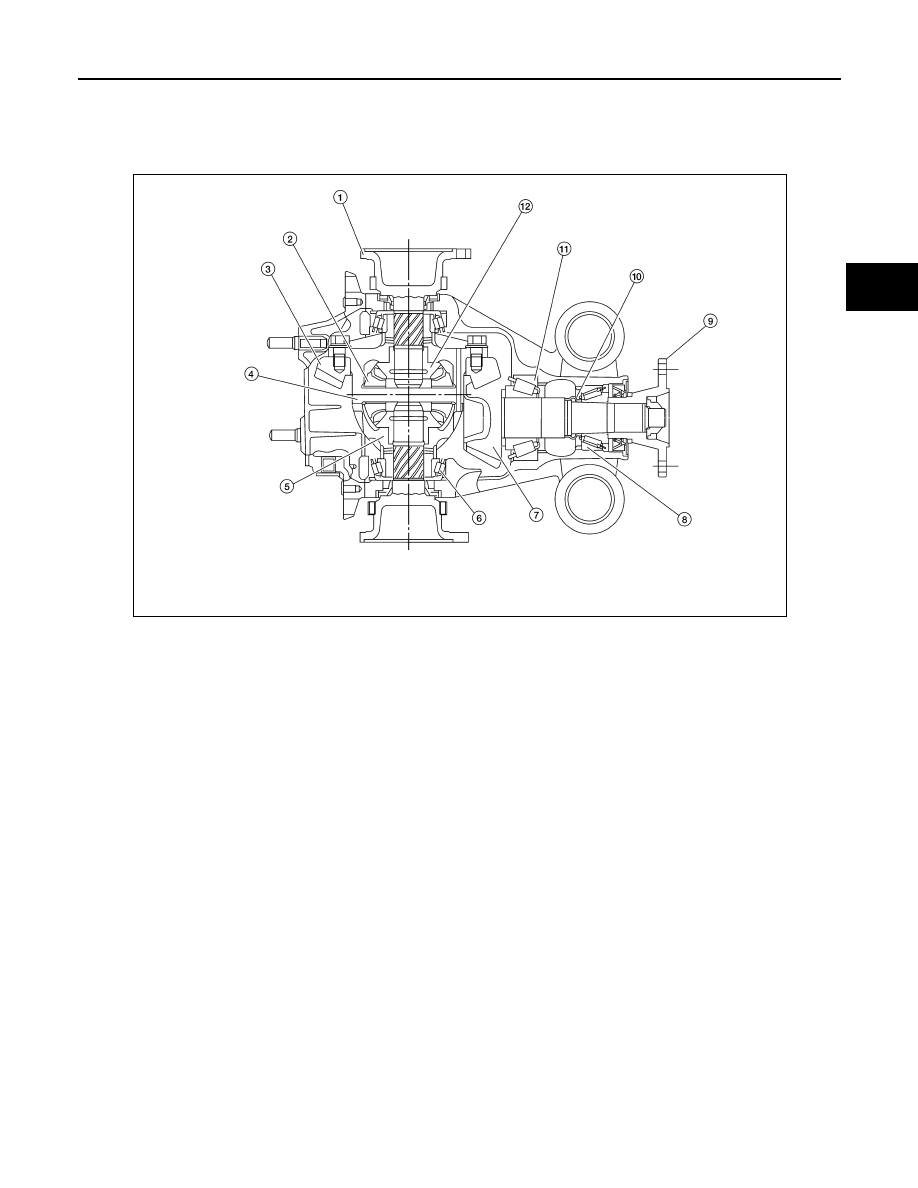
Cross-Sectional View
INFOID:0000000005148929
1.
Side flange
2.
Pinion mate gear
3.
Drive gear
4.
Pinion mate shaft
5.
Differential case
6.
Side bearing
7.
Drive pinion
8.
Drive pinion front bearing
9.
Companion flange
10. Collapsible spacer
11. Drive pinion rear bearing
12. Side gear
WDIA0119E
DLN-244
< ON-VEHICLE MAINTENANCE >
[REAR FINAL DRIVE: R230]
DIFFERENTIAL GEAR OIL
ON-VEHICLE MAINTENANCE
DIFFERENTIAL GEAR OIL
Changing Rear Differential Gear Oil
INFOID:0000000005148930
DRAINING
1. Stop the engine.
2. Remove the drain plug and gasket from the rear final drive
assembly to drain the differential gear oil.
3. Install the drain plug with a new gasket to the rear final drive
assembly. Tighten to the specified torque. Refer to
.
CAUTION:
Do not reuse gasket.
FILLING
1. Remove the filler plug and gasket from the rear final drive
assembly.
2. Fill the rear final drive assembly with new differential gear oil
until the level reaches the specified level near the filler plug hole.
3. Install the filler plug with a new gasket on it to the rear final drive
assembly. Tighten to the specified torque. Refer to
.
CAUTION:
Do not reuse gasket.
Checking Rear Differential Gear Oil
INFOID:0000000005148931
OIL LEAKAGE AND OIL LEVEL
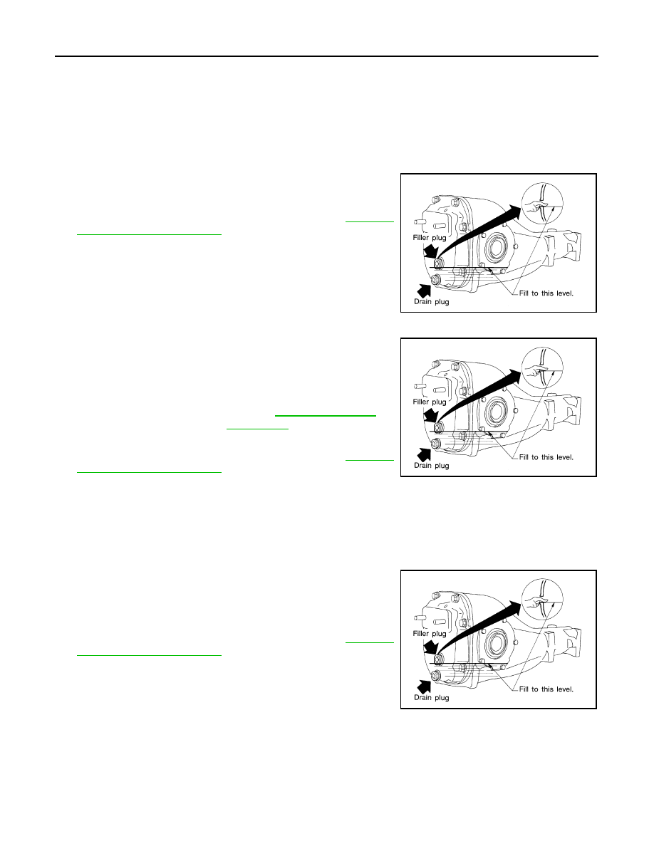
1. Make sure that differential gear oil is not leaking from the rear final drive assembly or around it.
2. Check the differential gear oil level from the filler plug hole as
shown.
CAUTION:
Do not start engine while checking differential gear oil level.
3. Install the filler plug with a new gasket on it to the rear final drive
assembly. Tighten to the specified torque. Refer to
.
CAUTION:
Do not reuse gasket.
LLIA0068E
Differential gear oil
grade and capacity
LLIA0068E
LLIA0068E
FRONT OIL SEAL
DLN-245
< ON-VEHICLE REPAIR >
[REAR FINAL DRIVE: R230]
C
E
F
G
H
I
J
K
L
M
A
B
DLN
N
O
P
ON-VEHICLE REPAIR
FRONT OIL SEAL
Removal and Installation
INFOID:0000000005148932
REMOVAL
1. Remove the drive shafts from the rear final drive assembly. Refer to
RAX-10, "Removal and Installation"
2. Remove the side flanges and side oil seals. Refer to
DLN-247, "Removal and Installation"
3. Remove the rear propeller shaft. Refer to
DLN-196, "Removal and Installation"
4. Measure the total preload torque. Refer to
DLN-253, "Disassembly and Assembly"
.
NOTE:
Record the total preload torque measurement.
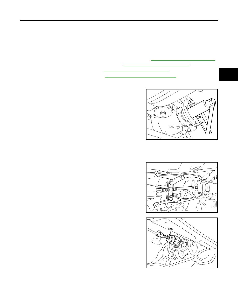
5. Remove the drive pinion lock nut using suitable tool.
6. Put matching marks on the companion flange and drive pinion using paint.
CAUTION:
Use paint to make the matching marks. Do not damage the companion flange or drive pinion.
7. Remove the companion flange using suitable tool.
8. Remove the front oil seal using Tool.
INSTALLATION
SDIA1142E
SDIA1054E
Tool number
: KV381054S0 (J-34286)
SDIA0485E
DLN-246
< ON-VEHICLE REPAIR >
[REAR FINAL DRIVE: R230]
FRONT OIL SEAL
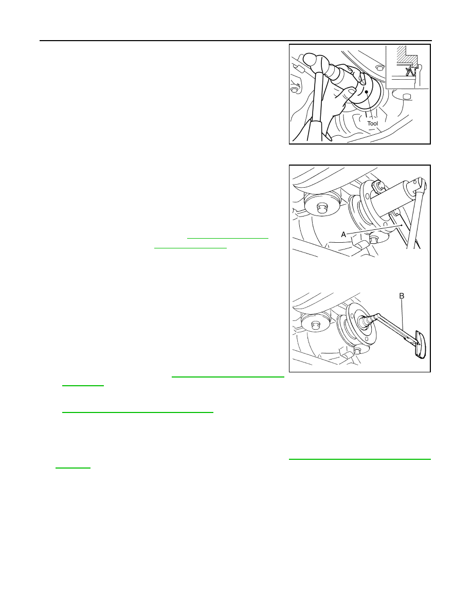
1. Apply multi-purpose grease to the lips of the new front oil seal.
Then drive the new front oil seal in evenly until it becomes flush
with the gear carrier using Tool.
CAUTION:
• Do not reuse front oil seal.
• Do not incline the new front oil seal when installing.
• Apply multi-purpose grease to the lips of the new front oil
seal.
2. Install the companion flange to the drive pinion while aligning the matching marks.
3. Apply anti-corrosive oil to the threads of the drive pinion and the
seating surface of the new drive pinion lock nut. Then adjust the
drive pinion lock nut tightening torque using suitable tool (A),
and check the total preload torque using Tool (B).
• The total preload torque should be within the total preload
torque specification. When not replacing the collapsible
spacer, it should also be equal to the measurement taken dur-
ing removal plus an additional 0.56 N·m (0.06 Kg-m, 5 in-lb).
• If the total preload torque is low, tighten the drive pinion lock
nut in 6.8 N·m (0.69 Kg-m, 5ft-lb) increments until the total pre-
load torque is met.
CAUTION:
• Do not reuse drive pinion lock nut.
• Apply anti-corrosive oil to the threads of the drive pinion
and the seating surface of the new drive pinion lock nut.
• Adjust the drive pinion lock nut tightening torque to the
lower limit first. Do not exceed the drive pinion lock nut
.
• Do not loosen drive pinion lock nut to adjust the total preload torque. If the total preload torque
exceeds the specifications, replace the collapsible spacer and tighten it again to adjust. Refer to
DLN-253, "Disassembly and Assembly"
• After adjustment, rotate drive pinion back and forth 2 to 3 times to check for unusual noise, rota-
tion malfunction, and other malfunctions.
4. Installation of the remaining components is in the reverse order of removal.
CAUTION:
Check the differential gear oil level after installation. Refer to
DLN-244, "Checking Rear Differential
.
Tool number
: ST15310000 ( — )
PDIA0565E
Tool number
B: ST3127S000 (J-25765-A)
Total preload torque: Refer to
.
WDIA0380E
Нет комментариевНе стесняйтесь поделиться с нами вашим ценным мнением.
Текст