Infiniti I35 (A33). Manual — part 215
Diagnostic Procedure
NHEC0851
1
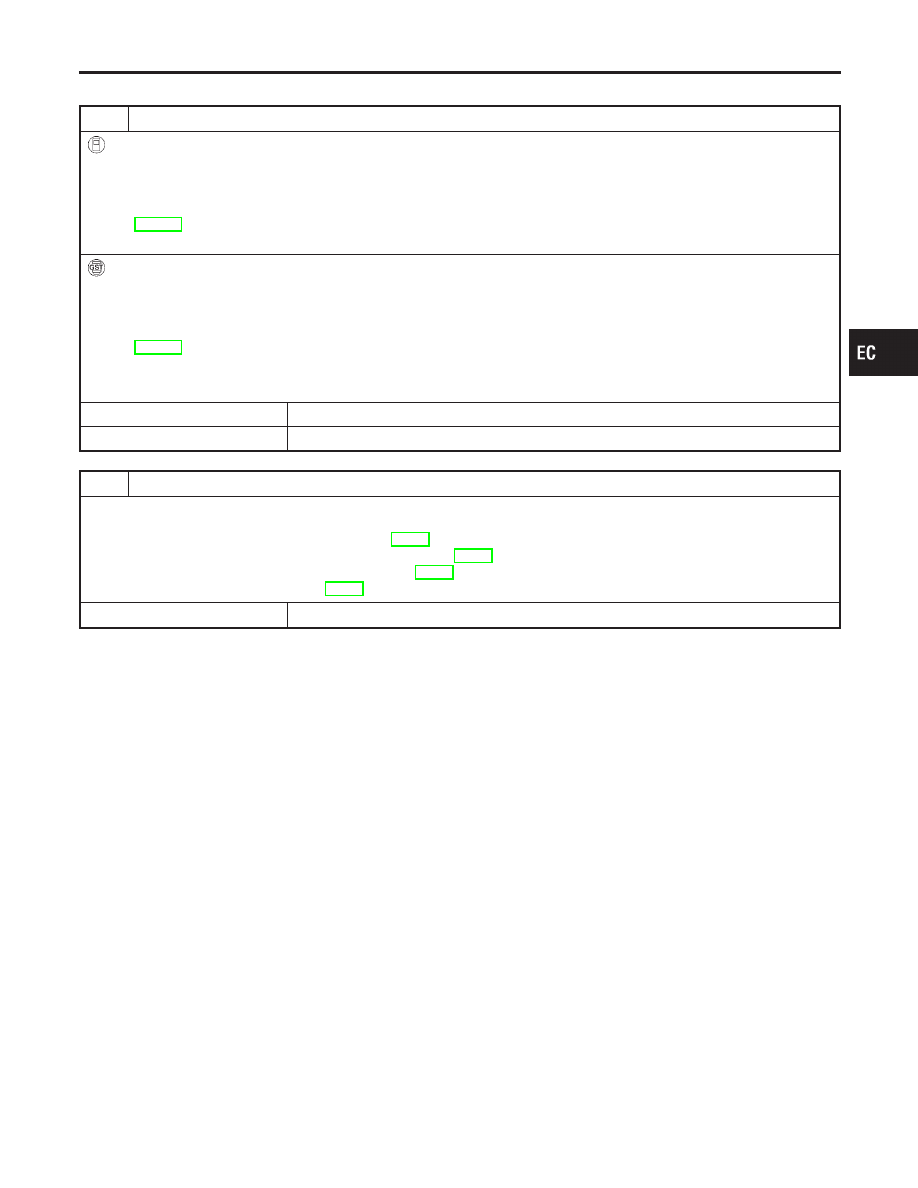
INSPECTION START
With CONSULT-II
1. Turn ignition switch ON.
2. Select “SELF DIAG RESULTS” mode with CONSULT-II.
3. Touch “ERASE”.
4. Perform “DTC Confirmation Procedure”.
See EC-200.
5. Is the 1st trip DTC P0107 or P0108 displayed again?
With GST
1. Turn ignition switch ON.
2. Select MODE 4 with GST.
3. Touch “ERASE”.
4. Perform “DTC Confirmation Procedure”.
See EC-200.
5. Is the 1st trip DTC P0107 or P0108 displayed again?
Yes or No
Yes
©
GO TO 2.
No
©
INSPECTION END
2
REPLACE ECM
1. Replace ECM.
2. Perform initialization of IVIS (NATS) system and registration of all IVIS (NATS) ignition key IDs. Refer to “IVIS (INFINITI
VEHICLE IMMOBILIZER SYSTEM — NATS)”, EC-90.
3. Perform “Accelerator Pedal Released Position Learning”, EC-70.
4. Perform “Throttle Valve Closed Position Learning”, EC-70.
5. Perform “Idle Air Volume Learning”, EC-70.
©
INSPECTION END
GI
MA
EM
LC
FE
AT
AX
SU
BR
ST
RS
BT
HA
SC
EL
IDX
DTC P0107, P0108 ABSOLUTE PRESSURE SENSOR
Diagnostic Procedure
EC-201
SEC266C
SEF012P
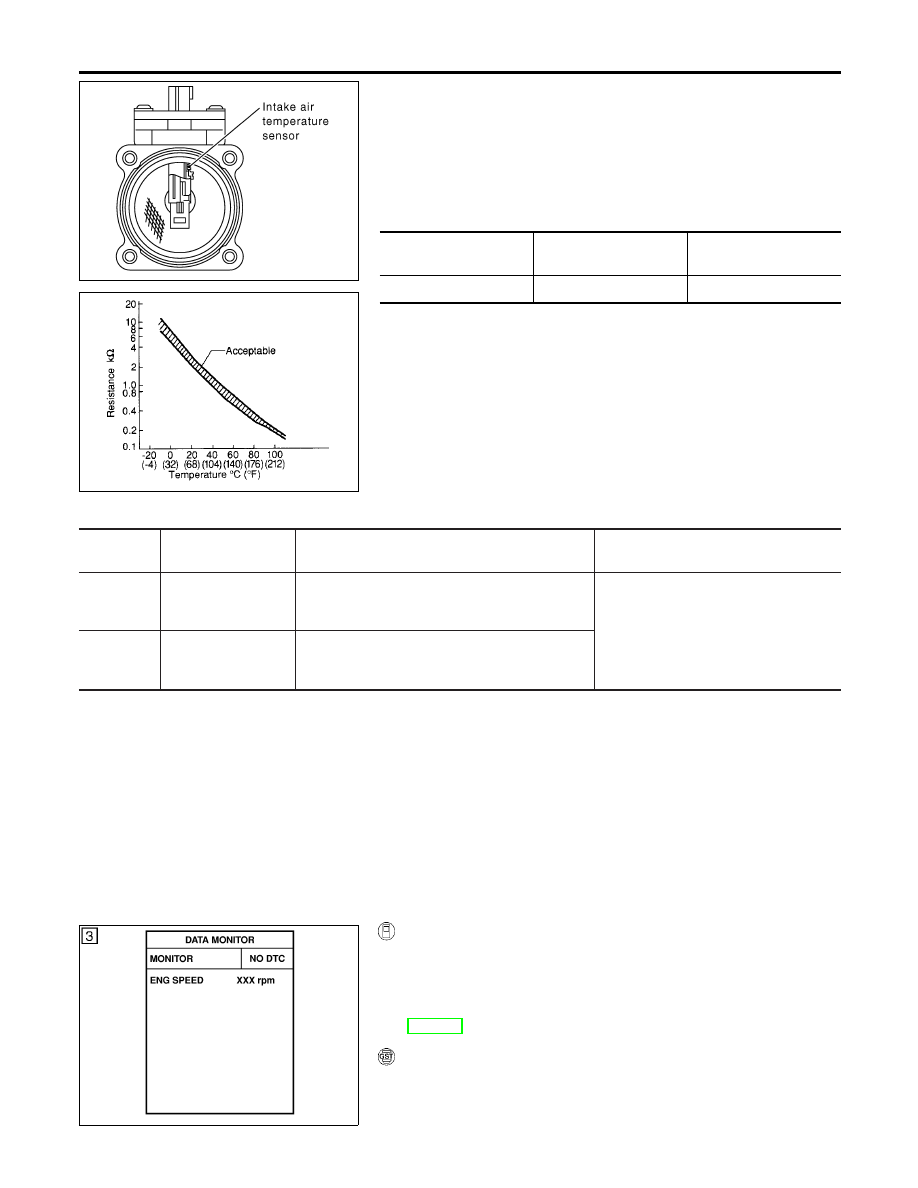
Component Description
NHEC0852
The intake air temperature sensor is mounted to the air duct hous-
ing. The sensor detects intake air temperature and transmits a sig-
nal to the ECM.
The temperature sensing unit uses a thermistor which is sensitive
to the change in temperature. Electrical resistance of the thermistor
decreases in response to the temperature rise.
<Reference data>
Intake air
temperature
°C (°F)
Voltage*
V
Resistance
k
Ω
25 (77)
3.32
1.9 - 2.1
*: This data is reference value and is measured between ECM terminal 66 (Intake
air temperature sensor) and body ground.
CAUTION:
Do not use ECM ground terminals when measuring input/
output voltage. Doing so may result in damage to the ECM’s
transistor. Use a ground other than ECM terminals, such as
the ground.
On Board Diagnosis Logic
NHEC0853
DTC No.
Trouble diagnosis
name
DTC Detecting Condition
Possible Cause
P0112
0112
Intake air temperature
sensor circuit low
input
An excessively low voltage from the sensor is sent
to ECM.
I
Harness or connectors
(The sensor circuit is open or
shorted.)
I
Intake air temperature sensor
P0113
0113
Intake air temperature
sensor circuit high
input
An excessively high voltage from the sensor is
sent to ECM.
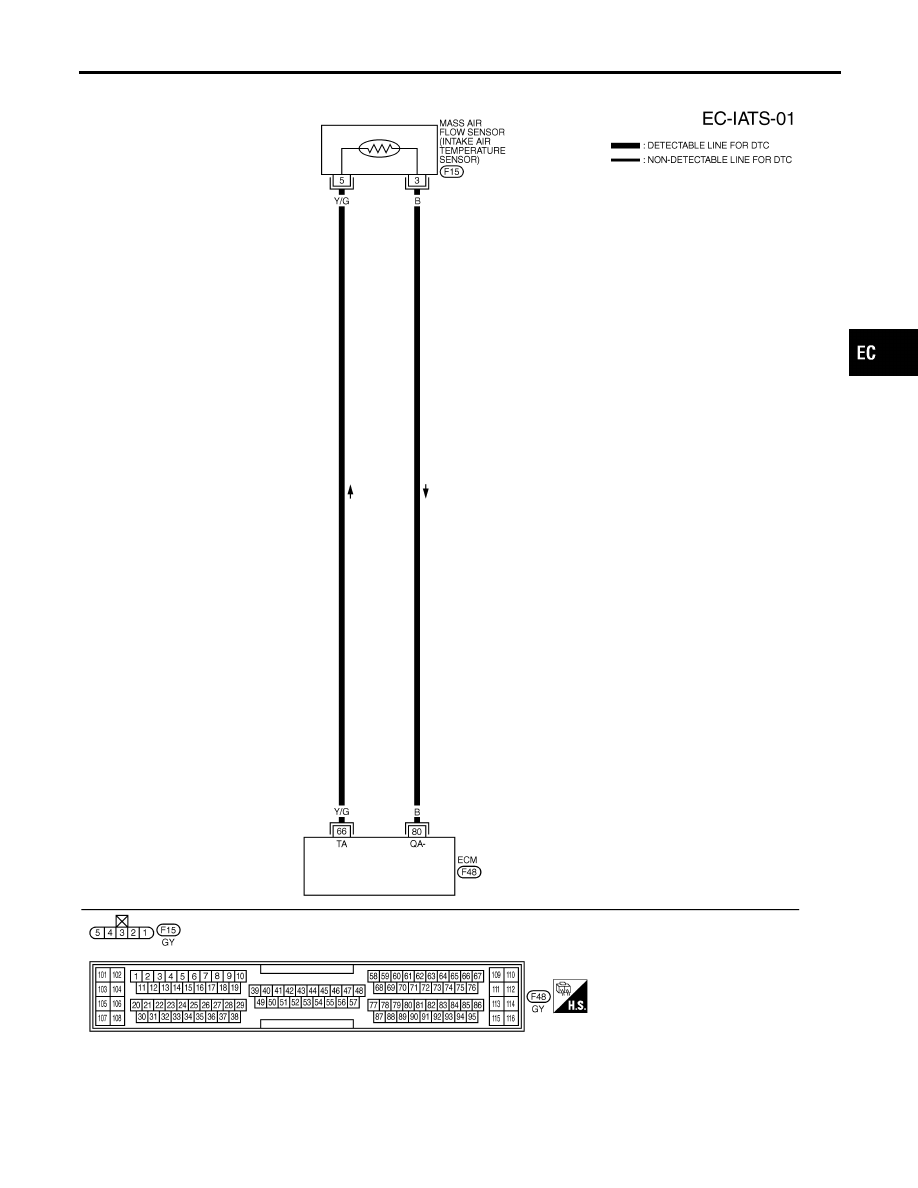
DTC Confirmation Procedure
NHEC0854
NOTE:
If DTC Confirmation Procedure has been previously conducted,
always turn ignition switch OFF and wait at least 10 seconds before
conducting the next test.
SEF058Y
WITH CONSULT-II
NHEC0854S01
1)
Turn ignition switch ON.
2)
Select “DATA MONITOR” mode with CONSULT-II.
3)
Wait at least 5 seconds.
4)
If 1st trip DTC is detected, go to “Diagnostic Procedure”,
EC-204.
WITH GST
NHEC0854S02
Follow the procedure “With CONSULT-II” above.
DTC P0112, P0113 IAT SENSOR
Component Description
EC-202
Wiring Diagram
NHEC0855
MEC532D
GI
MA
EM
LC
FE
AT
AX
SU
BR
ST
RS
BT
HA
SC
EL
IDX
DTC P0112, P0113 IAT SENSOR
Wiring Diagram
EC-203
Diagnostic Procedure
NHEC0856
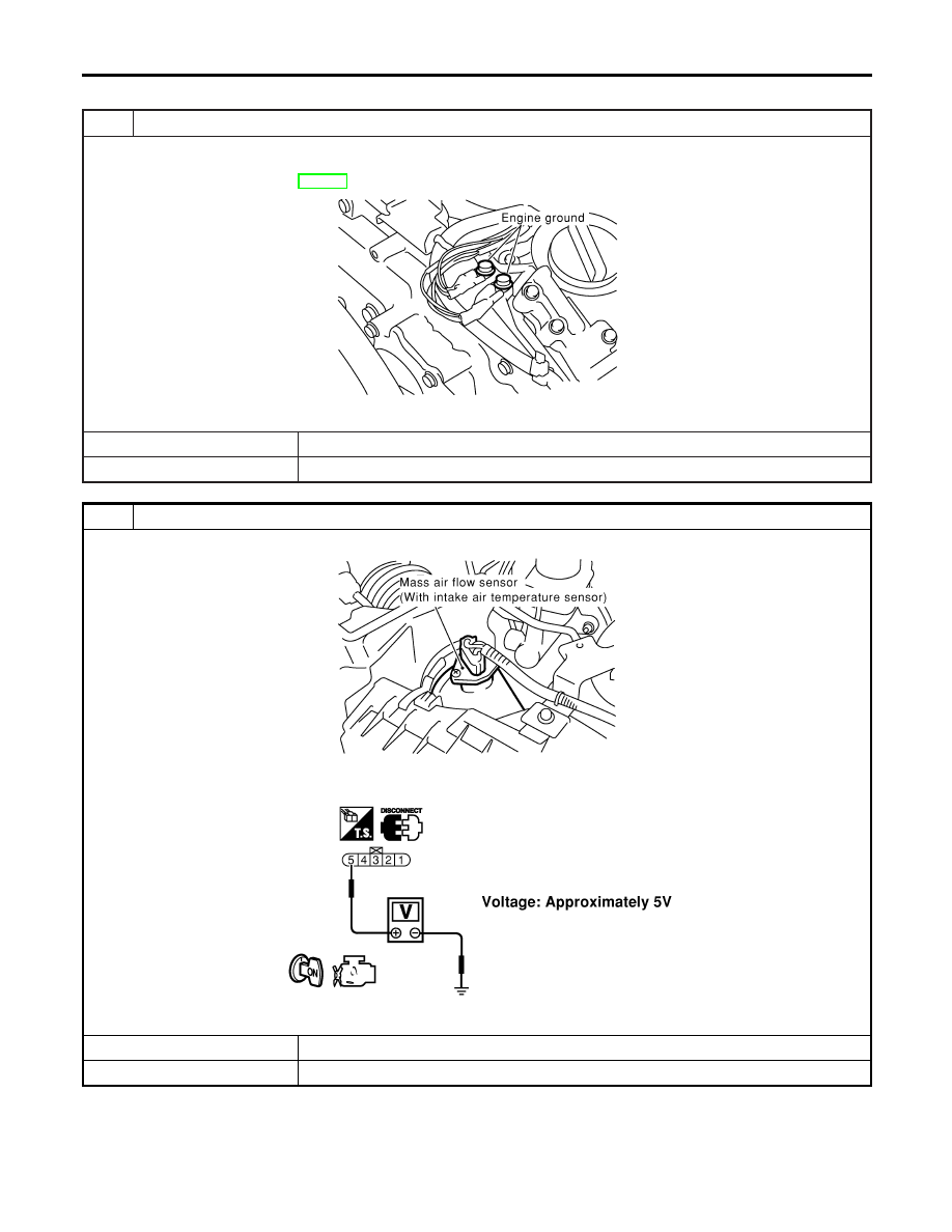
1
CHECK GROUND CONNECTIONS
1. Turn ignition switch OFF.
2. Loosen and retighten two engine ground screws.
Refer to “Ground Inspection”, EC-160.
SEC047D
OK or NG
OK
©
GO TO 2.
NG
©
Repair or replace ground connections.
2
CHECK INTAKE AIR TEMPERATURE SENSOR POWER SUPPLY CIRCUIT
1. Disconnect intake air temperature sensor harness connector.
SEC055D
2. Turn ignition switch ON.
3. Check voltage between terminal 5 and ground.
SEC104D
OK or NG
OK
©
GO TO 4.
NG
©
GO TO 3.
DTC P0112, P0113 IAT SENSOR
Diagnostic Procedure
EC-204
Нет комментариевНе стесняйтесь поделиться с нами вашим ценным мнением.
Текст